# Astro / Astro Max
{% embed url="" %}
The Freefly Astro is a compact professional multi-rotor built for enterprise and industrial work. Flown with the Pilot Pro controller, it runs an enterprise PX4-based flight stack and carries an onboard mission computer, RTK-capable GNSS, and swappable payloads.
This guide will be continuously updated with the latest information.
# Getting Started
How to get set up for a successful and safe first flight!
{% stepper %}
{% step %}
### Unboxing and Powering Your Astro
Open up the Astro case and you will see the Astro, a quick start guide, and the controller.
Remove the[ Pilot Pro controller](https://docs.freeflysystems.com/ecosystem/controller/pilot-pro) from the case, peel off the sticker from the controller screen, and press the power button twice to power it on. The Pilot Pro app will automatically open.
Pull the Astro out of the case, and set it down on a hard, stable surface.
Align one [SL8 battery](https://docs.freeflysystems.com/ecosystem/power/superlight-batteries) onto the Astro, and slide it into place with enough pressure to hear two clicks. This means that the battery is electrically connected to the Astro.
If you have a [compatible payload](https://docs.freeflysystems.com/ecosystem/payloads/payloads-overview#freefly-payloads), such as the [Sony LR1](https://docs.freeflysystems.com/ecosystem/payloads/lr1-payload), you should [connect your payload](https://docs.freeflysystems.com/ecosystem/payloads/payload-maintenance/installing-removing-payloads) before powering on the Astro.
{% hint style="danger" %}
The Smart Dovetail is not designed for hot-swapping payloads. Ensure that the Astro is powered off when connecting or removing payloads.
{% endhint %}
Once your payload is connected and secured, press the button on the battery once to wake the battery, then again to send power to the Astro.
{% hint style="warning" %}
Powering Astro with only 1 battery will prevent arming, making it much safer to have powered on while the propellers are installed. This is not a substitute for the absolute safety of removing propellers.
{% endhint %}
{% endstep %}
{% step %}
### Getting Hardware Charged and Ready
You should have received batteries in a separate shipment. The chargers for these batteries are going to be located in the Astro case, under the battery foam insert.
Connect the Astro batteries to the chargers and charge until complete.
Using the included 65W charger, plug in the Pilot Pro controller using the left-most USB-C port, and charge until complete.
Finally, ensure that your Astro [firmware is up to date](https://docs.freeflysystems.com/astro/maintenance/software-release-notes/software), and Pilot Pro has the [latest updates](/ecosystem/controller/pilot-pro/maintenance/software-and-firmware-updates).
{% endstep %}
{% step %}
### Learn How to Operate Astro
While your batteries and controller charge, read the [Flight section of this wiki](/astro/pilots-operating-handbook/operation), and learn how to control Astro.
If you are getting started with the **NDAA/Blue** version of the Astro, make sure to read the Doodle radio notes in our [Pilot Pro docs](/ecosystem/controller/pilot-pro/operating-handbook/radio-modules/doodle-labs-radio-module), as well as the different configurations and parameters in [DIU Blue sUAS](/astro/other-user-manuals/compliance/diu-blue-suas).
Learn about common workflows like [Photogrammetry Mapping](https://docs.freeflysystems.com/ecosystem/workflows/photogrammetry-mapping) and [LiDAR Mapping](https://docs.freeflysystems.com/ecosystem/workflows/lidar-mapping). Visit our [workflows page](/ecosystem/workflows/photogrammetry-mapping) for all our guides on how to put Astro to work.
Check out the [Freefly Astro Training Playlist](https://www.youtube.com/playlist?list=PLlKTld1e-W1wUvac10cbtM5Aru1su0QOO) on YouTube for some visual instruction.
{% hint style="warning" %}
Pilot skill with [Manual Mode](/astro/pilots-operating-handbook/flight-modes#manual) is required for[ Emergency Procedures](/astro/pilots-operating-handbook/emergency-procedures#emergency-procedure-checklists).
{% endhint %}
{% endstep %}
{% step %}
### Go Flying!
To ensure that the Pilot is using best practices, there is a quick checklist card included in the Astro case. The digital version is found in[ Part 2 - Operation](/astro/pilots-operating-handbook/operation#astro-flight-checklist).
Freefly also offers [official Astro Training](https://store.freeflysystems.com/collections/astro/products/astro-training) for up to 5 students at a time!
If you'd like to review the [flight logs](https://docs.freeflysystems.com/ecosystem/software/flight-logs), you can download and analyze them any time.
Now that you have completed your first flight, dive in, learn the details, and put Astro to work!
{% endstep %}
{% endstepper %}
# System Overview
Astro is the next generation of Freefly aircraft, which emphasizes expandability and customization to make sure it can stand up to all challenges thrown its way while still being the reliable workhorse drone that Freefly pilots know and love.
## Key Components
### Astro Aircraft Layout

### Astro Transmitter
{% tabs %}
{% tab title="Pilot Pro" %}
The current iteration of Astro ships with [**Pilot Pro**](https://store.freeflysystems.com/products/pilot-pro)**,** our custom controller. For more information, check the [Pilot Pro wiki](https://freefly.gitbook.io/pilot-pro-public/).
{% endtab %}
{% tab title="Herelink Controller" %}
Astro shipped with the [Herelink](/astro/other-user-manuals/ecosystem/components/pilot-handsets#herelink) controller as the pilot handset before late 2023. It runs a custom version of [Auterion Mission Control](/astro/pilots-operating-handbook/essential-software/auterion-mission-control) as its flight software.
{% endtab %}
{% endtabs %}
### SuperLight Battery
SuperLight Lithium-ion batteries are designed and manufactured by Freefly. You can find more information on the battery in the [SuperLight Battery](https://docs.freeflysystems.com/ecosystem/power/superlight-batteries) section of the wiki.
## Astro LEDs
There are 5 total status LEDs on the Astro. The 4 boom LEDs at the end of each arm show constant lights in most circumstances. By default, the rear two boom LEDs are red, and the front two boom LEDs are green. These LEDs will blink as the battery gets low, and blink quickly if there is an error.
The Astro uses a multi-color status indicator LED to communicate aircraft status on the ground. This LED is located on the front-left boom of the aircraft (pictured below in blue on boom 4). See the table below for complete information on the color codes
Location of the Status Indicator LED (Blue)
### Status Indicator LED Color Codes
Color
Meaning
Detail
Solid Blue
Armed, No GPS Lock
Indicates vehicle has been armed and has no position lock from the GPS. Position, Mission and Return flight modes are not available.
Pulsing Blue
Disarmed, No GPS Lock
Indicates vehicle is disarmed and has no position lock from the GPS. Position, Mission and RTL flight modes will not be available until GPS lock is acquired.
Solid Green
Armed, GPS Lock
Indicates vehicle has been armed and has position lock from the GPS. All flight modes are available.
Pulsing Green
Disarmed, GPS Lock
Indicates vehicle is disarmed and has position lock from the GPS. All flight modes will be available.
Solid Purple
Failsafe Mode
Indicates an error has been encountered during flight and the vehicle will activate the Failsafe Action (Return To Launch by default).
Solid Amber
Low Battery Warning
Indicates a battery voltage below threshold.
Flashing Red
Error / Setup Required
Indicates an error, typically an issue with sensor calibration or autopilot configuration.
# Flight Part 1 - Flight Modes
### Flight Modes
{% embed url="" %}
{% hint style="info" %}
Note that this video features the legacy Herelink controller with the original Astro. However, the flight modes and their behavior are unchanged unless otherwise noted in this guide.
{% endhint %}
Astro offers several flight modes with varying levels of assistance to the pilot.
Flight mode can be changed via the buttons on the Pilot Pro/Herelink or the AMC app on the handset/PC. See the documentation for the equipment you're using to become familiar with the buttons/switches involved.
{% tabs %}
{% tab title="Pilot Pro" %}
Manual mode switch buttons on the Pilot Pro controller
Manual mode switch buttons along the bottom of the Herelink controller.
{% endtab %}
{% endtabs %}
{% hint style="success" %}
Manual Mode may be necessary to react to emergency situations. Pilots should be proficient in Manual Mode. Position, Altitude, and Return Mode are assistive only and are not a replacement for pilot skill and preparedness.
{% endhint %}
{% hint style="warning" %}
Always neutralize the control input sticks on the pilot handset when switching between control modes to prevent unexpected aircraft movement.
{% endhint %}
### Pilot-controlled Modes
{% tabs %}
{% tab title="Position" %}
Position Mode Button on Pilot Pro
In Position Mode, when the sticks are centered, the aircraft will maintain its position over a point on the ground and maintain altitude, correcting for disturbances.
In Position Mode, the pitch/roll stick commands the speed of the drone relative to the ground. The further upward the pitch/roll stick, the faster Astro will fly forward. When the pitch/roll stick is pulled downward, Astro will fly backward. Similarly, the pitch/roll stick will move the drone in the left and right directions when moved to the left and right.
The throttle stick commands vertical speed. The further upward the throttle stick, the faster Astro will climb. Conversely, the lower the throttle stick position, the faster Astro will descend. Deflecting the throttle stick left and right controls the yaw rate, with the speed of rotation proportional to stick deflection.
{% hint style="info" %}
Position Mode requires a strong GPS signal. If a weak signal is present, Astro will not enter Position Mode.
If the signal deteriorates, such as near buildings or under dense tree cover, the aircraft will automatically revert to Altitude mode.
{% endhint %}
{% hint style="danger" %}
Flight using Position Mode in areas of degraded GPS signal, such as near buildings or under dense tree cover, is not recommended. The automatic reversion to Altitude Mode can cause unexpected, abrupt changes in flight behavior.
{% endhint %}
{% endtab %}
{% tab title="Altitude" %}
Altitude Mode Button on Pilot Pro
Similar to Position mode, the pitch/roll stick moves Astro laterally relative to the ground and the throttle stick commands vertical speed and yaw. However, while the drone can hold its vertical position using the barometer, lateral speed is not controlled by the autopilot in Altitude mode. Astro will drift with the wind, will not stop immediately after lateral movement, and will probably not hold a single point above the ground without pilot input.
{% hint style="info" %}
The aircraft holds altitude above Mean Sea Level (MSL) by default. It is not aware of terrain height changes or obstacles without additional configuration and equipment.
{% endhint %}
{% endtab %}
{% tab title="Manual" %}
Manual Mode Button on Pilot Pro
In Manual Mode, when the pitch and roll stick is centered, the aircraft will attempt to remain level and will drift with the wind. The aircraft will require constant throttle adjustment to hold altitude.
In Manual Mode, the pitch and roll stick controls the aircraft angle. The further upward the pitch stick, the further Astro will tilt forward. When the pitch stick is pulled downward, Astro will tilt backward. Similarly for roll in the left and right directions. Lateral speed is not controlled by the autopilot.
The throttle stick controls motor speed directly. Deflecting the throttle stick left and right controls the yaw rate. The speed of yaw rotation is proportional to stick deflection.
#### Manual Mode Settings
The hover throttle setting controls the amount of thrust Astro produces when the throttle stick is centered. The default setting of 34% will hover the aircraft with no payload. A setting of approximately 40% will hover with 1500 grams of payload.
Adjust this setting in AMC on the pilot handset or PC:
1. Enable [Advanced Mode ](https://freefly.gitbook.io/astro-public/pilots-operating-handbook/essential-software/auterion-mission-control/amc-vehicle-setup/advanced-vehicle-setup#activating-advanced-mode)
2. Vehicle Setup > Tuning
#### Learn Manual Mode
{% embed url="" %}
{% endtab %}
{% tab title="Position Slow" %}
Position Slow Mode Button on Pilot Pro
Position Slow acts just like regular Position Mode, but helps to give your flying more control over speed of movement. With the dials on the top of the Pilot Pro, you can now adjust velocity rates on the fly! Whether flying for tower inspections or a cinematic sweep, Position Slow helps give finesse to the pilot to achieve this with ease.
{% hint style="info" %}
The gimbal's dial on the left is always active regardless of mode
{% endhint %}
{% hint style="warning" %}
Position Slow was added in Astro v1.4.6 when the Pilot Pro was introduced and has not been tested on the Herelink controller. While it may be accessible depending on software version, you will not have options to change speeds dynamically that you do on the Pilot Pro. To map Position Slow to the D button, open AMC and under Advanced > Flight Modes, set Flight Mode 5 to Position (Slow). Next, enter the Herelink settings by swiping down from the top of the screen and clicking the Herelink stats. Go to the "BUTTONS" tab and change "D short press" from channel 10 to 14, then hit save.
{% endhint %}
{% endtab %}
{% endtabs %}
### Autonomous Modes
{% tabs %}
{% tab title="Return" %}
Return Mode Button on Pilot Pro
Return Mode commands Astro to climb to the Return Altitude, fly back to the Home Point in a straight line, and land. Return Mode requires GPS.
Return Altitude is set by the pilot at AMC > Vehicle Setup > Safety. Please note that if Astro is above the Return Altitude when Return Mode is initiated, it will maintain altitude instead of dropping to the return altitude.
The Home Point is set to the GPS coordinates where Astro is armed. Home Point is reset every time Astro is armed.
By default, Return Mode is activated automatically by some Failsafes.
{% hint style="warning" %}
Before every flight, think through the path the aircraft will take if Return Mode is activated, and adjust settings to arrange for safe behavior.
For example, activating Return Mode while flying under an obstacle lower than the Return Altitude will cause a collision when the aircraft attempts to climb to Return Altitude. In some cases, it may be possible to set a lower Return Altitude, and in other cases, it may not be possible to use Return Mode.
{% endhint %}
{% hint style="info" %}
It is possible to change from Return to Position Mode by moving the sticks, except if Return Mode was activated by the low battery failsafe. In that case, press another flight mode button to change out of Return Mode.
{% endhint %}
In most cases, RTL mode will travel to the predetermined RTL altitude, travel over the home point, and automatically descend to land. However, if the aircraft is close to the home point, the behavior will be slightly different in order to save time and reduce the amount of distance Astro will need to move.
* If Astro is directly over the home point at the time of RTL, it will land without gaining altitude regardless of its current altitude.
* If Astro is within a few meters of the home point, it will move directly above the home point and begin landing.
* If Astro is within 20m altitude and less than 20m ground distance from the home point, it will go to 20m altitude, move over the home point, and land.
* If Astro is between 20-35m altitude and less than 20m ground distance from the home point, it will maintain altitude, move over home point, and land.
* If Astro is more than 35m altitude or more than 20m ground distance from the home point, it will go to the set RTL altitude, move over the home point, and land.
{% endtab %}
{% tab title="Takeoff" %}
Takeoff Mode arms the aircraft, automatically climbs to the Takeoff Altitude, and enters [Hold Mode](https://docs.px4.io/v1.12/en/flight_modes/hold.html) (a.k.a. loiter or hover).
Takeoff Mode can be engaged via the button in the AMC app Fly view, optionally changing Takeoff Altitude via the slider, then holding/sliding to confirm. Takeoff Mode can also be engaged during a mission, for example as the first command.
{% hint style="info" %}
Takeoff Mode requires a GPS lock.
{% endhint %}
{% hint style="info" %}
Moving the sticks while in Hold Mode (i.e. after the aircraft has finished climbing) will cause a change to Position Mode. This makes it easy to take control without pressing the Position Mode button.
{% endhint %}
{% endtab %}
{% tab title="Landing" %}
### Landing Mode
Landing Mode causes Astro to descend and land directly below the position where Land Mode is engaged. Once on the ground, Astro will disarm.
Landing mode can be engaged via the button on the AMC app Fly screen. You'll need to hold the button down to confirm the switch.
Landing Mode is often the last command in a mission. It can also be engaged by a failsafe, such as low battery level, or loss of signal.
{% hint style="info" %}
Land Mode requires GPS when engaged manually.
When Land Mode is engaged by a failsafe, and GPS is not available, the autopilot behavior will be similar to Altitude Mode and the aircraft may drift horizontally as it descends.
{% endhint %}
{% hint style="info" %}
Moving the sticks will cause a change to Position Mode unless Landing Mode is engaged by a Failsafe (e.g. critical battery level). See the [Safety and Failsafes section](broken://pages/-LaNWMwiqb_UzRIMSvUW) for more details.
When activated by a low battery failsafe, Return and Landing Mode cannot be overridden by stick movement. They can be overridden by pressing a flight mode button (e.g. Position).
{% endhint %}
{% endtab %}
{% tab title="Mission" %}
Mission Mode allows Astro to execute a predefined autonomous waypoint mission that has been uploaded to the flight controller via AMC. For more information on all the different options and abilities built into the Mission Mode, see the AMC docs, sections such as:
* [Planning a mission](https://freefly.gitbook.io/astro-public/astro/pilots-operating-handbook/software/auterion-mission-control/amc-plan#example-mission)
* [Flying a mission](https://docs.auterion.com/auterion-mission-control/fly/flying-a-mission)
* [Remove a mission from the aircraft](https://docs.auterion.com/auterion-mission-control/plan/plan-ui-overview#file-sync-tools)
{% hint style="danger" %}
Starting a mission can cause the aircraft to arm itself and take off without any further pilot input. Before starting a mission, ensure that the aircraft is clear of obstacles in the propeller arc and flight path.
{% endhint %}
If a mission is interrupted (for example, by the pilot switching to Position mode), the Fly view will prompt to resume the mission. If a prompt is not shown, open the [Action Menu](https://docs.auterion.com/auterion-mission-control/fly/fly-view-ui-overview#fly-tools) and select "Resume Mission".
{% hint style="warning" %}
Astro must have a GPS lock before takeoff to set a valid home position to start a mission. Mission mode will be unavailable if the aircraft takes off before a GPS lock is achieved. The pilot must land and rearm with a GPS lock to enable it.
{% endhint %}
{% hint style="warning" %}
Depending on what Astro firmware version you're on, you may or may not be able to move sticks to interrupt Return Mode
Before Astro version 1.4.6, moving the flight sticks on the controller will interrupt Return and Mission mode.
For Astro version 1.4.6-1.5.18, moving the flight sticks will not interrupt these modes.
In 1.6.14 and later this setting was re-introduced as an op-in setting that's disabled by default, and by default stick movements will not interrupt Return Mode
To change this behavior, you can toggle [Advanced Mode](https://freefly.gitbook.io/astro-public/astro/pilots-operating-handbook/software/auterion-mission-control/amc-vehicle-setup/advanced-vehicle-setup#activating-advanced-mode) and change the COM\_RC\_OVERRIDE parameter to 1 in Vehicle Setup.
These changes were made as a response to feedback that accidental stick movements were interrupting these flight modes erroneously along with a userbase that wanted this behavior back.
{% endhint %}
{% endtab %}
{% endtabs %}
# Flight Part 2 - Operation
{% hint style="warning" %}
Make sure you understand Astro's [Emergency Procedures](/astro/pilots-operating-handbook/emergency-procedures) and understand how to operate the drone in [Manual Mode](/astro/pilots-operating-handbook/flight-modes#manual) before taking flight.
{% endhint %}
## Astro Flight Checklist
Below is our recommended Astro flight checklist, which covers the main considerations you need to be aware of before, during, and after operation.
{% file src="/files/-MfEfOVaVGz7lVmPbGBx" %}
Astro Checklists and EPs - v5.pdf
{% endfile %}
We also offer this checklist as a [Google Sheet template](https://docs.google.com/spreadsheets/d/1fzej5xve3mPZBkT5TpqMw7kgLpMkx0kWQzTIOoPZfCs/edit?usp=sharing) to allow for a more customized experience. For example, you might want to add specific items to better reflect your company's safety procedures, workflow, payload, or region.
***
## Before Flight
### Powering On the Transmitter
{% tabs %}
{% tab title="Pilot Pro" %}
If you have a Tab 3 (red button on the tablet) press and hold the small black button on the edge of the tablet to turn it on
If you have a Tab 5 (green button on the tablet) press the power button on the Pilot Pro twice
{% hint style="warning" %}
Pilot Pro will automatically open the Pilot Pro App. Once the Astro is running and everything shows as connected, switch over to the AMC app
{% endhint %}
{% endtab %}
{% tab title="Legacy Herelink" %}
Press and hold the power button below the screen until you see the Herelink logo appear
{% endtab %}
{% endtabs %}
### Powering On the Astro
{% embed url="" %}
How to power the Astro
{% endembed %}
The Astro can be powered with either one or two batteries. One battery will put the Astro into Bench Mode to prevent arm for benchtop operations, and two batteries will allow for flight
{% hint style="warning" %}
Bench Mode: Astro will only arm (i.e. spin the motors) if 2 batteries are installed. When powering Astro for non-flying purposes (e.g. bench testing), connect only one battery.
Bench mode is not a substitute for the absolute safety of removing propellers.
{% endhint %}
To power on the Astro, connect at least one SL8 battery by sliding it along the rails on top of the aircraft until you hear two clicks. Once connected, press the button on the battery twice to turn it on. If you have two batteries connected, they will both automatically power on when you turn on one of them.
### Checking Battery Levels
{% tabs %}
{% tab title="First Tab" %}
With Pilot Pro, AMC will show the Astro's current battery levels. Tap on the battery icon for more information, such as remaining flight time.
{% hint style="info" %}
The battery level for the RC will almost always report 100% at all times, because the Pilot Pro keeps the tablet fully charged.
{% endhint %}
{% endtab %}
{% tab title="Legacy Herelink" %}
Once the transmitter and Astro are connected, the AMC app indicates Astro's battery level and the battery level of the handset in the status bar.

{% endtab %}
{% endtabs %}
### Issues Preventing Arming
You may occasionally encounter issues that will prevent Astro from arming:
#### Compass Cal
If AMC asks you to calibrate the compass and won't allow you to take off, follow the [instructions to recalibrate sensors](/astro/maintenance/standard-maintenance-procedures/calibration-and-tuning#sensor-calibration) in an area without significant magnetic interference (far from large metal structures or magnetic/electric installations).
#### Everything else
Check if the AMC message you're encountering is on our [Error/Warning Spreadsheet](https://docs.google.com/spreadsheets/d/1DXkk0BmRx9qLbjpBt2KgKYFOQhEGUTcyyQB6rOmb4ac/edit#gid=0) and follow the associated instructions. If you're still experiencing the issue, please reach out to for further troubleshooting.
***
## Arming and Disarming
Astro's propulsion system has two fundamental states: Disarmed and Armed. These states are displayed on the Astro through the LED's on the boom arms.
| State | Definition | Indication |
| -------- | ------------------------------------------- | ----------------------------------------------- |
| Disarmed | Safe mode, no spinning propellers | Boom LEDS dim |
| Armed | Aircraft will spin propellers, ready to fly | Boom LEDs bright (100% or user specified level) |
Astro can be armed with or without GPS.
{% hint style="info" %}
Pro Tip: Wait for GPS lock even if you don't plan to use Position Mode because Return Mode relies on GPS.
{% endhint %}
{% hint style="danger" %}
Before arming, ensure people and other obstacles are clear of the propellers. Be prepared for Astro to take off.
{% endhint %}
The transition between Armed and Disarmed can be done either [through AMC](https://freefly.gitbook.io/astro-public/pilots-operating-handbook/emergency-procedures#advanced-arming-methods) or with the sticks on the pilot handset. (The pilot's handset default configuration is [Mode 2](https://docs.px4.io/master/en/getting_started/rc_transmitter_receiver.html#types-of-remote-controls).)
| State | Input |
| --------------- | ------------------------------------------------------------------------------------- |
| Arming (Mode 2) | Hold the throttle stick down and right for 2 seconds. |
| Disarming | When the aircraft has landed, continue holding the throttle stick down for 2 seconds. |

{% hint style="info" %}
It is not possible to disarm via the normal method while in flight.
To disarm during flight, perform an [Emergency Stop](https://freefly.gitbook.io/astro-public/astro/pilots-operating-handbook/emergency-procedures#emergency-stop).
{% endhint %}
{% hint style="info" %}
If Astro does not arm, check [Auterion Mission Control (AMC) for errors or warnings](/astro/pilots-operating-handbook/essential-software/auterion-mission-control).
{% endhint %}
{% hint style="info" %}
Use only the throttle stick to Arm & Disarm. Astro will not respond to two-stick input (i.e. DJI arming gesture).
{% endhint %}
Missions may Arm and Disarm the aircraft automatically. For example, if a mission is started while the aircraft is disarmed on the ground, the aircraft will arm and take off.
### Automatic Disarm Methods
Under these conditions, Astro will automatically disarm.
| Method | Astro behavior |
| -------------------------------- | ------------------------------------------------------------------------------------------------------------------------------------------------------ |
| Ground timeout before taking off | If Astro sits on the ground at idle throttle for 10 seconds, it will automatically disarm. |
| Land mode | If Astro is in Land Mode, and detects a landing, it will disarm after 2 seconds. For example, this applies if the last command in a mission is "Land". |
***
## Taking off
Position Mode is best for taking off in most cases, as it offers the most stabilization. However, it is certainly possible to take off in Altitude, Manual, and Mission modes as well.
For 5 seconds after takeoff, the maximum pitch and roll angles are reduced to 12 degrees.
After takeoff, promptly climb out of ground effect (i.e. to 3 meters / 12 feet of altitude) to avoid snagging landing gear on the ground.
#### Takeoff best practices:
{% tabs %}
{% tab title="In Position and Altitude Mode" %}
After arming, allow the throttle stick to return to the center. The propellers will remain idle. When ready to take off, raise the throttle stick. The propellers will spin up and the aircraft will take off.
{% endtab %}
{% tab title="In Manual Mode" %}
After arming, hold the throttle stick straight down with no Yaw input. When ready to take off, raise the throttle stick slowly. The propellers will accelerate as soon as the throttle stick moves. As the throttle approaches the mid-point, there will be enough thrust to take off. Continue raising the throttle to achieve a brisk takeoff.
{% endtab %}
{% endtabs %}
***
## Landing
Position Mode is best for landing in most cases, as it offers the most stabilization. However, it is certainly possible to land in Altitude and Manual modes as well. The aircraft behaves a little differently in each mode.
{% hint style="danger" %}
Do not hand catch Astro. The aircraft is designed to be landed on hard flat surfaces. Hand catching can result in serious injury or death.
{% endhint %}
In Position and Altitude Modes, at altitudes below 7 meters, the maximum vertical speed is reduced to 0.7 m/s (from the normal value of 2 m/s).
Astro will disarm automatically after the autopilot detects a landing. Landing detection brings together input from several sensors to determine when it is safe to disarm.
{% hint style="warning" %}
If the landing is not detected (i.e. the props do not stop after touchdown), perform the [Emergency Procedure for Landing Detector Failure](/astro/pilots-operating-handbook/emergency-procedures#emergency-stop-amc).
{% endhint %}
#### Landing best practices:
{% tabs %}
{% tab title="Landing In Position Mode" %}
Bring the aircraft to a hover > 2 meters over the spot where landing is desired. Pull the throttle stick straight down as far as it goes, without any pitch, roll, or yaw commands. Astro's landing sensor will manage the speed of your descent. After touchdown, hold the throttle stick down until Astro disarms and the propellers stop.
At altitudes below 2 meters, the maximum pitch/roll angle is reduced to 12 degrees. This prevents abrupt maneuvers that might cause a tip-over.
{% hint style="warning" %}
Pitch, Roll, or Yaw commands very near the ground can cause crashes or tip-overs.
{% endhint %}
{% endtab %}
{% tab title="Landing In Altitude Mode" %}
Landing in Altitude Mode is different than Position Mode because the pilot is responsible for managing lateral velocity. The autopilot will control the throttle to manage the descent rate.
Bring the aircraft to a hover > 2 meters over the spot where landing is desired. Give minimal pitch and roll commands to minimize both lateral speed and minimize pitch/roll angle. Pull the throttle stick down. After touchdown, hold the throttle stick down until Astro disarms and the propellers stop.
At altitudes below 2 meters, pitch/roll angle limits are reduced to 12 degrees. This reduces the likelihood of abrupt maneuvers that might cause a tip-over.
{% endtab %}
{% tab title="Landing In Manual Mode" %}
Landing in Manual Mode is different than Position or Altitude Mode because the pilot is responsible for managing vertical *and* lateral velocity.
Bring the aircraft to a hover > 2 meters over the spot where landing is desired. Give minimal pitch and roll commands necessary to minimize both lateral speed and minimize pitch/roll angle. Reduce throttle to allow the aircraft to descend slowly.
As Astro nears the ground and enters ground effect, the pilot will often need to reduce the throttle to keep the aircraft descending. Once the aircraft has touched down, the operator should reduce the throttle to zero promptly so that it settles on the ground instead of possibly bouncing or dragging the landing gear. Hold the throttle stick down until Astro disarms and the propellers stop
{% endtab %}
{% endtabs %}
***
## Battery Changes / Hotswaps
{% hint style="danger" %}
While Astro will recognize that the battery is low and perform a failsafe action (return to launch by default), the aircraft has no context of situations that might prevent a safe landing before the battery is exhausted. For instance, if the aircraft is several miles away from the RTL point when the failsafe is triggered, there is a chance that there won't be enough battery life to return. \
\
It is the pilot's responsibility to determine the appropriate time for a battery change and to ensure the aircraft is safely grounded.
{% endhint %}
### Battery Changes
The Astro's batteries can be removed by pushing up on the grey tab on the back of the battery. This will unlock the battery, and allow you to slide it out.
{% hint style="info" %}
Astro's SL8 batteries do not need to be powered off before removal
{% endhint %}
### Hotswap
{% embed url="" %}
During some longer missions, you may find hotswapping batteries easier, which will keep the Astro powered on during the battery changing process. To hotswap batteries, remove one discharged pack from the drone and replace it with a charged pack. Enable the pack by pressing the power button twice, then replace the other discharged pack. Enable the second charged pack if it does not show "Hotswap" on the battery display screen.
The pilot may also adjust the [Low Battery Failsafe settings](https://docs.auterion.com/vehicle-operation/settings-and-maintenance/safety#low-battery) to activate Return Mode automatically at a level appropriate for the mission.
Upon landing, AMC will offer an option to "Resume Mission from Waypoint #". This will modify the mission by removing the waypoints already visited.
# Flight Part 3 - Emergency / Advanced
## General Guidance
**Human safety must be the top priority. Aircraft can be replaced. People cannot. Always prioritize the safety of yourself and others over the preservation of aircraft or equipment.**
Emergency situations are dynamic events, that will not often conform perfectly to the categories listed below. A thorough understanding of aircraft systems, proficiency in piloting the aircraft, and sound judgment will allow you to bring about the best possible outcome in an emergency.
The likelihood of an emergency can be reduced substantially through [proper aircraft maintenance](broken://pages/-MfEfk7y0P474WN5vrmM), the use of [checklists for normal procedures](broken://pages/-MfEfCAXYq5xABmbFcTc#checklists), and careful pre-flight planning. The likelihood of a safe flight often depends on the diligence of the pilot, both before taking off and during operation.
In general, if an emergency occurs, three basic actions can be applied to most situations:
1. Maintain aircraft control — Small emergencies can quickly escalate if the pilot is distracted attempting to troubleshoot the problem. Always maintain visual contact with the aircraft during an emergency to reduce the likelihood of losing orientation.
2. Analyze the situation — Once the aircraft is stabilized, assess the cause of the emergency.
3. Take appropriate action — In many cases, the appropriate action will be to land the aircraft as soon as possible. Aircraft can be replaced.
### Return Mode
Do not be over-reliant on [Return Mode](/astro/pilots-operating-handbook/operation#return) in emergency situations. The cause of the emergency may degrade performance or disable Return Mode. For example, loss of GPS disables Return Mode.
{% hint style="warning" %}
Depending on what Astro firmware version you're on, you may or may not be able to move sticks to interrupt Return Mode
Before Astro version 1.4.6, moving the flight sticks on the controller will interrupt Return and Mission mode.
For Astro version 1.4.6-1.5.18, moving the flight sticks will not interrupt these modes.
In 1.6.14 and later this setting was re-introduced as an opt-in setting that's disabled by default, and by default stick movements will not interrupt Return Mode
This change was made as a response to feedback that accidental stick movements were interrupting these flight modes erroneously. To change this behavior, you can toggle [Advanced Mode](https://freefly.gitbook.io/astro-public/astro/pilots-operating-handbook/software/auterion-mission-control/amc-vehicle-setup/advanced-vehicle-setup#activating-advanced-mode) and change the COM\_RC\_OVERRIDE parameter to 1 in Vehicle Setup.
{% endhint %}
## Emergency Procedure Checklists
The [Astro checklists](https://freefly.gitbook.io/astro-public/products/astro/pilots-operating-handbook/flight#checklists) contain concise instructions to follow to mitigate risk in the event of an in-flight emergency. Some of these situations are discussed in more detail below.
{% tabs %}
{% tab title="Orientation Loss" %}
### Loss of Orientation
If orientation is lost, neutralize inputs and activate position mode. Then work to identify the front of the aircraft.
We recommend identifying the front of the aircraft via a "guess and check" method of small roll right inputs alternating with yawing the aircraft 90 degrees at a time. We recommend a roll input rather than pitch because at a distance it is easier to see lateral motion than fore/aft motion.
If it is not possible to identify orientation, and it is safe to activate Return Mode, do so. By default in Return Mode, after climbing, the aircraft will yaw to put the front toward the direction of flight.
Resume flying or land as necessary.
{% endtab %}
{% tab title="Unexpected Behavior" %}
### Unexpected Aircraft Behavior
If Astro behaves unexpectedly, do the following: neutralize inputs, activate Position Mode, and observe the aircraft. If it is still flying in an uncommanded manner in Position or Altitude Mode, switch to Manual Mode.
In some cases, unexpected behavior is due to degraded GPS signal or erroneous sensor readings (e.g. compass error). In such cases, Return Mode may not behave reliably. Manual Mode does not rely on these sensors.
Land as soon as possible.
{% endtab %}
{% tab title="Landing Detector Failure" %}
### Landing Detector Failure
If the aircraft touches down, but hops back up into the air several times, or sits on the ground with the props continuing to spin, the autopilot may not have detected a landing. Climb and retry landing with a greater downward velocity.
{% hint style="info" %}
Landing the aircraft firmly will give the accelerometers and gyroscopes a sufficient contrast between flight and landing.
{% endhint %}
If an attempted landing is unsuccessful in Position and Altitude mode, land in Manual Mode.
If an attempted landing is unsuccessful in Manual Mode, perform an [Emergency Stop](/astro/pilots-operating-handbook/operation#emergency-stop) with the aircraft on the ground or as close as possible.
{% endtab %}
{% tab title="GPS Loss" %}
### Loss of GPS
If GPS is lost, flight modes that rely on GPS (Position, Return, Mission, etc) will not be available. If the aircraft is in Position mode when GPS is lost, the autopilot will switch to Altitude Mode. If the aircraft is in Return or Mission modes when GPS is lost, it will automatically start landing. Landing can be overridden by the pilot by changing modes to Altitude or Manual modes.
{% hint style="info" %}
It is the pilot's responsibility to be proficient with Altitude and Manual Mode and to have the aircraft configured to behave safely if GPS is lost.
{% endhint %}
Examples of behavior without GPS:
* If GPS is not available upon arming, no Home Point is set, and Return Mode is not available. Even if GPS becomes available while flying, Return Mode will not be available.
* If the pilot commands Return Mode, the aircraft will remain in Altitude or Manual Mode, and an error will be displayed on the pilot handset.
* If Land Mode is activated (e.g. by a failsafe), the aircraft will descend as though in Altitude mode, maintaining a consistent descent but drifting with the wind.
* If GPS is lost in Position, the aircraft will display a warning and switch flight mode to either Altitude Mode or Manual Mode, depending on the degradation of the signal and other sensors
* If GPS is providing altitude information (e.g. while using RTK GPS), and GPS is lost, the ability of Altitude Mode to accurately maintain altitude may be affected.
{% endtab %}
{% tab title="RC Loss of Signal (LOS)" %}
### RC Loss of Signal (LOS)
RC Loss of Signal (LOS) can occur if the pilot handset signal is degraded or stops, or if Astro does not receive the signal due to distance or interference (e.g. from obstacles or other radio signals).
If the signal is lost longer than the RC Timeout, a failsafe action will be triggered. The RC Timeout is quite short by default: 0.5 seconds. The pilot may not have time to react before the failsafe action is activated. By default, the failsafe action is Return Mode.
If the signal is lost, check the pilot's handset power and [antenna orientation](/astro/other-user-manuals/ecosystem/components/pilot-handsets#antennas). Antenna orientation is especially important when Astro is far from the pilot.
If the signal is recovered, the pilot will be able to take control via moving the sticks or pressing a flight mode button.
{% hint style="info" %}
RC Loss of Signal (LOS) is differentiated from Data Link Loss. LOS refers to the stream of SBUS data containing the pilot's inputs. Data Link refers to the stream of MavLINK messages. Astro routes both data streams through a single radio system. Please note that the AMC app needs to be in the foreground on the pilot handset during operation; Data Link will fail after 30 seconds and trigger a failsafe if the AMC app is closed or running in the background.
{% endhint %}
{% endtab %}
{% tab title="Video Loss" %}
### Loss of Video Signal
Loss of Video Signal can occur if the aircraft flies out of range or if it flies behind an object that interrupts the signal. Maintaining visual contact is the preferred method to re-establish control of the aircraft, either with the pilot seeing the aircraft or by the use of a visual observer.
Yawing the aircraft can help signal reception if the body of the aircraft is blocking the line of sight between the transmitter and receiver antennas.
If video signal or visual contact cannot be re-established, enable Return Mode to bring the aircraft back to signal reception range.
{% hint style="danger" %}
It is the responsibility of the pilot to see and avoid other aircraft, people, or obstacles. Always maintain a direct line of sight with Astro during flight, use visual observers as operations require, and follow local regulations regarding see-and-avoid requirements.
{% endhint %}
{% endtab %}
{% endtabs %}
## Emergency Stop
{% hint style="danger" %}
#### As a last resort, if it is not possible to land or control the aircraft, perform an Emergency Stop. If performed while flying, this will cause the aircraft to crash. Perform the Emergency Stop as far away from people as possible.
{% endhint %}
{% tabs %}
{% tab title="AMC" %}
### Emergency Stop - AMC
In AMC on the pilot handset or PC, tap the "Armed" button at the top center of the screen to display the Emergency Stop dialogue. Hold the Emergency Stop button for 4 seconds. This works on the pilot handset or PC.

{% endtab %}
{% tab title="Manual Override" %}
### Emergency Stop - Manual Override
In Manual Mode, hold the throttle stick down and left for 10 seconds.

{% endtab %}
{% endtabs %}
## Failsafes
Failsafe behavior and settings are configured in AMC. The [AMC documentation ](https://docs.auterion.com/vehicle-operation/settings-and-maintenance/safety)covers each failsafe and related settings in detail.
Some failsafes are discussed briefly below.
{% hint style="warning" %}
We strongly recommend using the default settings, changing only Return Altitude, unless you are an expert user and have tested the effect of changes thoroughly.
{% endhint %}
{% tabs %}
{% tab title="Low Battery" %}
### Low Battery
Battery level is evaluated from the State of Charge (SoC, e.g. 72%), not voltage (e.g. 23 Volts).
As the battery level becomes low, the autopilot can take action. The default settings do not interfere until the battery becomes quite low. Additionally, low battery failsafes are only able to estimate how long it will take the aircraft to return to the home point. This means it is the pilot's responsibility to be aware of the battery level and ensure the aircraft is on the ground.
State
SoC (default)
Action (default)
Warning
20%
Warning: Flash boom LEDs
Critical (>200m)
17-15%
Return Mode
Critical (<200m)
10%
Return Mode
Emergency
6%
Land Mode
{% hint style="info" %}
When activated by a low battery failsafe, Return and Land Mode cannot be overridden by stick movement. They can be overridden by pressing a flight mode button (e.g. Position).
{% endhint %}
{% endtab %}
{% endtabs %}
## Error and Warning Indication
The aircraft communicates the presence of errors and warnings primarily through Auterion Mission Control (AMC) [status indicators](https://docs.auterion.com/auterion-mission-control/fly/fly-view-ui-overview#vehicle-status-indicators-top-bar) on the pilot handset or PC. Many messages are accompanied by an audible message (e.g. "Return Flight Mode"). Additionally, Astro boom LEDs will flash when the battery level is low.
Status messages, including errors and warnings, are stored in Flight Logs. After any emergency, review the log to determine the source of the problem.
If the meaning of an error or warning is not clear, please [contact Freefly Support](https://freeflysystems.com/support/astro-support). Share as much detail as possible, including [sharing the flight log](/astro/pilots-operating-handbook/essential-software/auterion-suite#flight-logs).
## Advanced Arming Methods
| Method | Input |
| ---------------------- | --------------------------------------------------------------------------------------------------------------------------------------- |
| AMC App, pilot handset | Tap the Arm button (top center) and hold to confirm. |
| Mission | If a mission starts with the takeoff command, and the aircraft is disarmed, the aircraft will arm itself when the mission is initiated. |
{% hint style="info" %}
Arming via the AMC app in Manual Mode is not recommended. In Manual Mode, the aircraft should be armed while the throttle stick is held at the minimum position. This is difficult to achieve while using an app GUI.
{% endhint %}
# Auterion Software
Freefly has partnered with Auterion to provide customers an easy way to fly using Auterion Mission Control, as well as manage their fleet using Auterion Suite.
### [Auterion Mission Control](https://docs.freeflysystems.com/astro/~/revisions/mTpQspqCOZxVfR8CbzgE/pilots-operating-handbook/essential-software/auterion-mission-control)
**Auterion Mission Control (AMC)** is the mission planning software pre-installed on Pilot Pro.
### [Auterion Suite](https://docs.freeflysystems.com/astro/~/revisions/mTpQspqCOZxVfR8CbzgE/pilots-operating-handbook/essential-software/auterion-suite)
**Auterion Suite** is an *optional* fleet management web app that is fully compatible with Astro. It has useful features like automatic flight log uploads, image uploads, and more. Learn more by visiting [Auterion's documentation](https://docs.auterion.com/vehicle-operation/auterion-suite-fleet-management).
# Auterion Mission Control
Auterion Mission Control (AMC) is a ground control station application for pilots. Use it to plan and fly missions, control the aircraft in flight, and configure Astro on the ground. AMC comes pre-installed on Pilot Pro and is also available as a desktop app for PC, Mac, and Linux.
See Auterion's full documentation for AMC [here](https://docs.auterion.com/vehicle-operation/auterion-mission-control).
# AMC - Fly
The fly screen shows a live feed of either the camera feed or an overhead map view.
## Camera View
This screen includes a live camera feed, telemetry, and camera/gimbal control. You can also launch uploaded missions or take off using the touch screen.
## Map View
This screen shows the nearby satellite map, as well as the currently uploaded mission when applicable.
## Pre-Flight Checklist
An optional checklist to assess the requirements of flying a safe mission or manual flight. This checklist can be accessed by tapping the Vehicle box near the top-left corner of the screen. Tapping the yellow boxes turns them green, allowing you to manually verify each item before takeoff.
Red items represent warnings or errors. Some items will prevent takeoff if there is an associated warning or error, such as insufficient battery power. Others will allow for takeoff with some limited usage. In the example below, there is no GPS signal, so the aircraft will only be capable of taking off in Manual mode.
# AMC - Plan
## Example Mission
{% tabs %}
{% tab title="Video" %}
{% embed url="" %}
{% endtab %}
{% tab title="Text" %}
The default view for a new mission as shown on the Plan screen.
After selecting the Takeoff icon along the left-hand side of the Plan screen.
Using the Waypoint tool to create the first waypoint for the drone to move towards after takeoff.
After selecting the Pattern button along the left, this pop-up appears prompting you to select the type of pattern. In this example, we will pick the Survey option.
After selecting Survey, a tool appears on the bottom of the screen allowing you to define the area of your survey.
We defined the area of our survey by moving the white dots at the corners of the square.
After we have a pattern we are happy with, we can select the Return button on the left to ask the drone to return to the launch point.
{% endtab %}
{% endtabs %}
### Front Overlap
Definition: The amount that each image overlaps with the previous sequential image; effectively, you are taking pictures more frequently on each straightaway of your mission. \
\
Benefit: The higher the front overlap, the more consistent your resulting map will likely be, as the stitching software will have an easier time connecting the discrete images together.
Tradeoff: You will be taking more pictures, many of which are redundant to an extent. This takes up more storage and takes more time to process. \
\
When changing this value, keep in mind that your photo interval needs to be greater than or equal to 2.0 seconds. The USB drive cannot save large images any faster. \
\
Recommended value: 70%
### Side Overlap
#### Definition
The amount that each image overlaps with the adjacent images in a parallel leg of the mission. The higher the value, the closer each swath of the mission will be to its neighboring swath.
#### Benefit
Like front overlap, higher side overlap increases the consistency of your stitching software by introducing more redundant landmarks that help combine the two photos together.
#### Tradeoff
Due to the increased number of passes over the same area, increasing side overlap will also increase the duration of your mission. Unlike front overlap, increasing your side overlap percentage does not increase your photo interval, though it will still increase the total number of pictures taken.
Recommended value: 70%
### Altitude vs. Ground Resolution (GSD)
The Survey options ask you to select one: Altitude or GSD. These two options are directly proportional and can be selected based on the mission area and your requirements.
GSD, or Ground Resolution, is a general approximation of the fidelity of each image when compared to real-world measurements. For example, a ground resolution of 1 cm/px posits that every single pixel in the resulting map will be approximately 1 centimeter in length. \
\
This measurement can be calculated using the camera's resolution and the distance from the object being photographed. It stands to reason that if we have the desired ground resolution and the camera's resolution as known variables, the distance (or altitude of the aircraft) can be calculated as well!
Notice how changing the altitude or GSD sliders will also change the other option automatically. If you are using GSD, make sure that the resulting altitude is still clear of any obstacles.
Pattern Options
# Transfer Mission Plan and KML Files with Herelink
## Options for importing/exporting plans
* **Mission import/export:** AMC’s .plan files can be imported and exported. This is useful for creating missions on a computer, then importing all of them to Herelink at the same time
* **KML import:** KML files can be imported to AMC. This is useful for creating mission shape definitions in some software, then importing all of them to Herelink at the same time.
Important Note on importing:
* Zoom in to maximum level, then create a random survey shape. If you don’t zoom in, survey shape could be very large and could crash AMC
* Then click “import KML” on the right toolbar
* Survey shape will automatically change to the data defined in the KML import
* **KML export:** This is useful for exporting waypoints outside AMC. You won’t be able to import them back as KML, since these are waypoints, and not a shape definition.
## Procedures for transferring files to/from Herelink
### Method 1: Micro USB port
{% hint style="info" %}
This method may not work as expected on Mac. We recommend using Method 2 on Apple computers.
{% endhint %}
1\) Connect the Herelink via the Micro USB port to a computer.
2\) Turn on the Herelink.
3\) Drag down from the top to open the drop-down menu. Select “USB Charging this device”.
4\) Select “Transfer files”.
5\) The Herelink will appear on your computer as a device named “Optimus”.
6\) Upload flight plans into the following folder: Optimus > Internal shared storage > Documents > Auterion Mission Control > Missions
{% hint style="info" %}
If you aren't seeing the files you're expecting on the Herelink or computer, restart the Herelink.
{% endhint %}
### Method 2: Micro SD card (supports maximum 64GB)
1\) Upload flight plans onto the MicroSD card.
2\) Insert Micro SD card into the Herelink’s Micro SD Card slot.
3\) Drag down from the top to open the drop-down menu and select the Micro SD card device.
4\) Select the desired flight plan and select “Copy to…” or “Move to…”
5\) Select Optimus > Documents > Auterion Mission Control > Missions.
6\) Select “Copy” or “Move” to complete transferring.
# Terrain Follow
**Terrain Follow** is a feature commonly found in various flight simulation and drone control systems that enables an aircraft or vehicle to automatically adjust its altitude based on the contours of the terrain below. This capability is essential for maintaining safe and efficient flight paths over mountainous or uneven landscapes, preventing the risk of terrain collision. Enabling Terrain Follow enhances situational awareness and simplifies navigation by ensuring that the vehicle follows the natural topography without requiring constant manual altitude adjustments. This guide will walk you through the steps needed to enable and configure Terrain Follow, offering an improved and safer operational experience for pilots and operators.
{% hint style="warning" %}
Terrain Follow is only as effective as the elevation data it relies on and should not be considered a substitute for pilot vigilance. The system may not account for obstacles such as trees or buildings, which could pose a risk if not monitored manually by the operator. Therefore, while Terrain Follow enhances safety by adapting to terrain contours, pilots must remain attentive to their surroundings at all times.
{% endhint %}
{% hint style="info" %}
Terrain follow is only supported for Patterns and is not available on waypoint missions
{% endhint %}
## Setting Up a Terrain Follow Mission
{% tabs %}
{% tab title="Video" %}
{% endtab %}
{% tab title="Photos" %}
Navigate to the Plan screen
Start one of the pattern options
Navigate to the 'mountain' section
Enable Terrain Follow by checking the box
Indicating Terrain Follow is enabled, but it is downloading the terrain data
{% endtab %}
{% endtabs %}
## Offline Maps and Terrain Data
Terrain Follow requires the terrain data to be downloaded. The download can happen when you enable it on the mission, or you can preload the data. To download maps, please follow our [Offline Maps instructions](/astro/pilots-operating-handbook/essential-software/auterion-mission-control/amc-plan/offline-maps)
{% hint style="info" %}
Tablet on the Pilot Pro must be connected to the internet to download maps
{% endhint %}
## Changing Terrain Data Providers
By default we use Copernicus Elevation for our terrain provider. AMC also supports Mapbox for offline maps. To change your elevation data to use Mapbox, this can be changed in the offline maps settings by entering your Mapbox Access Token
Where to enter your Mapbox Access Token
Once you have this saved, you can now select Mapbox when downloading an offline map
Offline Map with Mapbox Elevation
# Offline Maps
**Using Offline Maps on the Ground Control Station (GCS)** allows operators to access detailed maps and navigate effectively without requiring an active internet connection. This feature is particularly useful in remote areas where a stable internet connection may not be available. By pre-downloading map data, operators can continue to plan and monitor missions, ensuring continuous situational awareness and flight control. This guide will walk you through the process of setting up and using offline maps on the GCS, helping you maintain reliable navigation capabilities in areas with limited connectivity.
## Downloading Offline Maps
Offline maps can be downloaded through the 'Offline Maps' section in the AMC settings. The vehicle will not need to be turned on to download maps, but the tablet will need to be connected to the internet. After maps are downloaded, they will be available without a network connection on the tablet. If terrain data is needed, make sure the elevation provider is selected when downloading maps.
{% tabs %}
{% tab title="Video" %}
Downloading Offline Maps in AMC
{% endtab %}
{% tab title="Photos" %}
Open AMC's Settings to Access the Offline Map Downloads
Click on 'Add New Set' to add an offline map
AMC Offlien Maps Download Menu
When downloading offline maps, you have the options to change the map provider as well as changing the zoom levels. The smaller you allow the zoom, the higher amount of dta it will use. You can see the estimated size the download will be under the zoom levels. If terrain data is needed, make sure the elevation provider is chosen during download.
{% endtab %}
{% endtabs %}
## Deleting Offline Maps
To delete an offline map, tap on the map's tile set, and you can delete or rename the map set
{% tabs %}
{% tab title="Video" %}
Deleting Offline Maps in AMC
{% endtab %}
{% tab title="Photos" %}
Access Downloaded Maps through AMC's settings
Select the tileset you want to remove. We will be removing tile set 003
Selecting a Tile Set
When the tile set is selected, you will have the options to rename or delete the tile set
Tile Set Options
Elevation tile sets are separate from elevation tile sets and will need to be removed separately
{% endtab %}
{% endtabs %}
# AMC - Vehicle Setup
## Summary
Provides a brief overview of the main vehicle setup bullet-points that pilots should consider before takeoff. If there is an issue with the sensors or radio, the green dots seen below will instead be red.
## Joystick
Currently, the only functionality of this screen is to change and test the functionality of the physical button on the top-right corner of the controller.
Use the dropdown to select the functionality of the button. Watch the box with the 0 in it while pressing the button to verify that it is working.
## Sensors
Select Compass, Gyroscope, or Accelerometer to recalibrate. Calibration is recommended for any sensors marked with a red dot.
## Radio
Displays a live view of the radio inputs. Allows you to switch between Mode 1 and Mode 2 control schemes (Mode 2 recommended).
## Safety
This screen is essential to operating Astro safely. Ensure that the altitude under Return To Launch Settings is higher than the tallest obstructing obstacle. For instance, if your mission takes place near a 65m tree, a return altitude of 60m is insufficient. If an RTL triggers while the aircraft and the landing point are on opposite sides of this tree and you are unable to regain control, it is unlikely that the aircraft will return to the ground safely in this scenario.
## Cellular
## WiFi
# Advanced Vehicle Setup
Changing these settings requires Advanced Mode, which is not recommended for most pilots. Key safety features and parameters that keep Astro airborne can be disabled if changes are made without understanding their purpose. Keep in mind that changing settings in this mode poses an increased risk to property and safety if not done with careful consideration and care.
## Activating Advanced Mode
To switch to Advanced Mode and see many of these options, repeatedly tap on the AMC icon in the top-left-hand corner of the app. After tapping about 6 times, a popup menu will appear asking if you would like to switch to Advanced Mode. The icon will change once Advanced Mode is active. \
\
You can return to Standard Mode by repeating the process of tapping the icon until the menu appears and selecting the option to switch to Standard Mode.
## Advanced Summary
## Advanced Airframe
## Advanced Sensors
Be very careful about the Autopilot Orientation setting when calibrating sensors in Advanced Mode. It should not be changed from the default value of ROTATION\_YAW\_270.
## Advanced Motors
## Advanced Safety
## Advanced Tuning
## Advanced Camera
# Parameters
## Accessing Advanced Parameters
{% hint style="danger" %}
Please exercise extreme caution before changing parameters. Do not operate Astro with edited parameters unless you are certain you know what you're doing or have been instructed to do so by a Freefly employee.
{% endhint %}
Parameters are only accessible after [enabling AMC's Advanced Mode](https://freefly.gitbook.io/astro-public/pilots-operating-handbook/essential-software/auterion-mission-control/amc-vehicle-setup/advanced-vehicle-setup#activating-advanced-mode)
{% tabs %}
{% tab title="Video Instructions" %}
{% embed url="" %}
Enabling Advanced Mode and accessing parameters
{% endembed %}
{% endtab %}
{% tab title="Text Instructions" %}
1. Enable AMC's advanced mode by rapidly tapping the AMC logo in the top left:
2. A popup to enable Advanced Mode will appear, confirm that you would like to switch to Advanced mode
3. Tap the AMC icon one more time to open the menu, and more options will now appear. Go into Advanced
4. Now scroll down to the bottom and choose Parameters, and parameters will now be accessible and searchable in the screen to the right
{% endtab %}
{% endtabs %}
## Advanced Parameter Commands
### Resetting Parameters to Factory Defaults
On occasion you may need to reset the parameters to the vehicle's default. To do this, once you navigate to parameters, click on Tools > Reset to vehicle's configuration defaults
### Loading Parameter Files
Especially in support situations, we may ask you to load a parameter file. To do this, the file will need to be copied into AMC's visible folder so that it can load the file. AMC will be looking for parameters under Documents > Auterion Mission Control > Parameters
To load the parameter file, go to the parameter page and go to Tools > Load from file. As long as the file is in the right location, it should show up and be selectable to import the parameter changes
# AMC - Photos
# AMC - User Account
# AMC - Settings
## General
## Comm Links
## Offline Maps
## Silvus
# Advanced Mode
By default, AMC hides features, settings, and menus that are not relevant for a drone operator or not intended to be changed by the end user. For development tasks, Auterion Mission Control can be switched into an advanced mode which enables additional menus and features, most notably:
* Analyze Tab -> MAVlink Console
* Analyze Tab -> MAVlink Inspector
* Vehicle Setup Tab
### Enable Advanced Mode in AMC
In order to switch into the advanced mode, **quickly tap the logo about 7 times** in the top left corner until you are prompted to confirm the change to Advanced Mode.
## MavLink
## Console
# Auterion Suite
A fleet management web app that works with Astro out of the box

### Overview
Auterion Suite is an optional, paid fleet management web app that is fully compatible with Astro. It has useful features like automatic flight log uploads, image uploads, and more. Learn more by visiting [Auterion's documentation](https://docs.auterion.com/vehicle-operation/auterion-suite-fleet-management).
Many features are available, such as:
* Managing your aircraft fleet
* Access detailed flight logs, and easily share them with Freefly Support
* Get software updates
* Cloud features like log upload, image upload, live streaming, and more.
{% hint style="info" %}
To start using Auterion Suite, you must [sign up for an account](https://docs.auterion.com/vehicle-operation/auterion-sign-up).
{% endhint %}
{% hint style="info" %}
Auterion Suite is *optional*. It will not prevent you from flying your aircraft.
There is a free version with limited functionality. A paid subscription is required to unlock all its features. For more information on pricing and features, see below.
{% endhint %}
### Basic (Free) Plan vs. Pro Plan
Basic (Free)
Pro
Price
$0
$77 per vehicle/month, billed annually
OR $95 per vehicle/month, billed monthly
Vehicles
Up to 2
Up to 15
Collaboration
Up to 5 users
Up to 40 users
Battery Monitoring
Up to 4 batteries
Up to 100 batteries
Missions
Up to 5 missions
Up to 100 missions
Pilot Certification Management
None
Yes
Reporting
Yes
Yes
Flight Logs
Up to 7 days
Unlimited
Log Download
No
Yes
Live Streaming
No
Yes
{% hint style="info" %}
After two vehicles, Auterion Suite's Basic plan will not allow additional vehicles to be registered. You will need to either [archive an existing vehicle](https://docs.auterion.com/vehicle-operation/auterion-suite-fleet-management/fleet-management/vehicles#archive), or purchase a Pro plan subscription.
{% endhint %}
For more plan details and updated pricing information, [contact Auterion](https://auterion.com/company/contact-us/).
### How to sign up for the Auterion Suite and Register your Astro
{% embed url="" %}
**This video covers the workflow to register your Astro with Auterion Suite.**
* Using a computer, connect a USB-C cable from your computer to the IO panel on the underside of the Freefly Astro.
* Power on the the Astro with one SL8 battery (NOTE: Using only one battery prevents the danger of accidentally arming the aircraft).
* **This physical connection to the Astro is required for security reasons as the Suite enables location data, live streaming, etc.**
* Using a web browser, go to the following address to connect to the Astro: `10.41.1.1`
* This page will allow the user to sign up for the suite as well as automatically register and claim the aircraft. Click "Register Now" or scan QR code for mobile signup.
* Note: This requires the vehicle to be online to generate a signup QR code otherwise it’ll say “internet required” for the registration prompt.
* [Connect the Astro to the internet](/astro/maintenance/network-and-connectivity) using either a WiFi or LTE network.
*
By default, Blue/NDAA Astros have WiFi and LTE disabled for DIU Blue compliance.
* If Astro is connected to the internet and plugged into the computer and `10.41.1.1` does not show the Register Now button, try refreshing your browser.
* Once complete, you should see the Astro unit listed under the "Vehicles" Section on the main dashboard of the Auterion Suite.
* Go Fly!
### Flight Logs
Astro's autopilot automatically creates log files that record the aircraft's flight path, inputs received, outputs sent, and more.
Log files are stored to aircraft's internal storage, which can be downloaded to a PC. If the Astro is configured to upload logs to Auterion Suite, you can view them any time Auterion Suite Fleet Management > Flights.
To learn more about how to access and analyze the different log files, please see [Flight Logs](/ecosystem/software/flight-logs).
#### Viewing Logs in Auterion Suite
The easiest way to view the logs is with an [Auterion Suite account](https://docs.auterion.com/vehicle-operation/auterion-sign-up) (Basic version is free).
[Navigate to a particular flight](https://docs.auterion.com/vehicle-operation/auterion-suite-fleet-management/flights) to see many plots showing data such as angles, position, speed, GPS quality, vibration, etc. It will also show the build information, parameter values, and any errors detected in the flight.
#### Sharing Flight Logs with Support
To share an uploaded flight log from Auterion Suite, use the "Share with Manufacturer" toggle. This sends the flight log directly to Freefly support.
This creates a support ticket with any information included in the log, statement on submission, and will link to the email associated with Auterion Suite. Be sure to add all relevant details to your submission.

### Privacy, Data Sharing, and Security
Freefly believes data generated by Astro, including flight logs, are your property. We think it's important that you are in control of your data, are confident in the measures taken to ensure security, and agree with how the data is used.
The Auterion Privacy Policy gives a layperson's description of how data can flow from Astro, through the Suite, and to partners you choose.
Briefly, when Astro is registered with a Suite account, you can choose to have flight logs automatically uploaded from the aircraft to Auterion servers when an internet connection is available. You can review this data in your Suite account. Auterion employees do not have access to your data. You may choose to share individual flight logs with Freefly Support via the Suite, for example to troubleshoot details of a specific flight.
* Freefly and Auterion understand the need for full data control and user privacy so we have built this platform for maximum user control.
* The Astro comes with hardware to support WIFI and LTE connections to the internet or other devices.
* If you do not want the LTE to connect, do not install a SIM card for data connection
* If you do not want the Astro to connect to WIFI, do not select any networks or present any passwords. You can also disable WIFI on the pilot handset.
* For security purposes the user needs to have physical access/connection to the Astro in order to register the aircraft to the Auterion Suite because the Auterion Suite enables log uploads, live unit status tracking, live video streaming etc.
{% hint style="info" %}
Learn more about the Astro's internet connections: [wifi](https://freefly.gitbook.io/astro-public/astro/pilots-operating-handbook/network-and-connectivity#wifi) and [LTE](https://freefly.gitbook.io/astro-public/astro/pilots-operating-handbook/network-and-connectivity#lte).
{% endhint %}
# Pro Tips and Limitations
It is possible to operate Astro close to the limits of performance by maintaining awareness of the performance envelope, how the aircraft behaves if the limits are exceeded, and best practices for operating in harsh environments.
This page reflects the limitations of the most current version. As the Astro platform matures, limitations are likely to change. For major changes that may affect these limitations, check the [release notes](https://freefly.gitbook.io/astro-public/products/astro/maintenance-manual/software-release-notes).
***
## Troubleshooting
Visit our [Troubleshooting Spreadsheet](https://docs.google.com/spreadsheets/d/1DXkk0BmRx9qLbjpBt2KgKYFOQhEGUTcyyQB6rOmb4ac/edit#gid=528435697) to look into additional solutions if you aren't finding what you're looking for on the wiki.
***
## Flight Control
For all flight modes except Manual, at altitudes below 2 meters, the tilt angle is reduced to 12 degrees and vertical speed is reduced to 0.7 m/s.
The purpose is to prevent tip-overs while landing but has the side effect of reducing speed if flying below the takeoff point (e.g. surveying from a high vantage point). We are working to correct this behavior.
***
## Continuous Operation
With eight (8) SL8 batteries, six (6) SL8 chargers, and access to power at your flight location, you can keep Astro in continuous operation. Two batteries fly the aircraft while the remaining six charge, so a freshly charged set is always ready when you land. Swap the packs, take off again, and put the depleted set back on the chargers.
{% hint style="warning" %}
In hot conditions, you will likely need an additional two batteries, as it may take some time to cool the recently flown batteries to an acceptable charging temperature (below 50°C).
{% endhint %}
For more information on batteries, click the page link below.
{% content-ref url="/pages/-MfEh5D4IenKOn6IDsdQ" %}
[Batteries](/astro/other-user-manuals/ecosystem/components/batteries)
{% endcontent-ref %}
***
## Radio Range and Interferences
Operating with a weak signal, whether due to interference or long range, can cause loss of link with the aircraft, which will engage failsafes. If you anticipate a weak signal situation, double-check that failsafes are set appropriately.
### Range
The range of Herelink and the Doodle radios on Astro is approximately 2 km in ideal conditions, assuming there are no interferences and the antennas are positioned correctly.
### Antenna Positioning
{% hint style="warning" %}
This is one of the simplest to miss and impact the range of the flight
{% endhint %}
#### **Pilot Pro**
Both the Doodle and Herelink radio modules on Pilot Pro use two blade antennas that are omni directional. It is important to follow these basic guidelines:
* Antennas should both point in the same direction.
* Antennas should point towards ground for best signal quality in most situations.
#### **Herelink GCS (Legacy):**
Herelink GCS has two types of antennas.
* Patch antenna (with a circular disk on top) is a directional antenna and should be pointed toward the aircraft
* Other antenna is omni-directional and it should be positioned pointing towards the ground or sky
### Interferences
Usable range depends heavily on the RF environment. Radio interference from nearby transmitters operating in the same frequency band, such as WiFi access points, can reduce both range and link quality. Physical obstructions affect the signal as well, such as trees, buildings, and terrain near the controller, near the aircraft, or directly in the line of sight between them can reduce range\
significantly.
### Multiple Aircraft
* Astro's Doodle radio configuration runs on dedicated peer to peer channels. In order to fly multiple Astros in the same airspace, make sure to scan channels and then set each Astro Doodle to a different channel.
* Astro's Herelink radios are channel hopping by default. 4 aircraft can fly simultaneously in the same airspace in practice. If more aircraft are present, interference can cause loss of radio link and control.
* If using the legacy Herelink GCS, you can set each Herelink to be on a dedicated channel
* If using the Pilot Pro with the Herelink radio, this feature is not yet available.
### High Power Radio Interference
Avoid using high-power, low-frequency radio transmitters (such as the RFD 900) mounted to Astro, as it can disrupt the normal function of the aircraft. For more information, see this [service bulletin](https://freeflysystems.com/knowledge-base/astro-sb002-high-power-radio-astro-interference).
***
## Environment
### Temperature
Astro can operate between -20 and 50 C. Position mode and survey flying are normal throughout the range. However, care is needed to operate at low and high temperatures.
Yellow region: Hovering and aggressive flights may give overtemp warnings. Follow the warning instructions.
Blue region: If batteries become too cold, state of charge will decline quickly and aircraft will enter Return or Land mode. Keep batteries warm, above 10 °C at takeoff, then self-heating will keep them warm.
{% tabs %}
{% tab title="Tips for operating in hot environments" %}
At high temperatures, the limiting factors are motor and battery temperatures. AMC will display a warning if the motors or batteries become too hot. Heed the warnings! Astro operates normally in forward flight up to 15 m/s with a full payload of 1500 grams.
Cooling air is your friend. The motors get much more cooling air in forward flight than in a hover. Overheat errors may occur when hovering because there is less airflow, or when flying aggressively because heating increases with current.
Batteries may require cooling before charging. Bring an extra set of batteries and chargers to enable continuous flying. If you connect batteries to the charger while cooling, they will automatically begin charging as soon as they have cooled sufficiently.
{% endtab %}
{% tab title="Tips for operating in cold environments" %}
At low temperatures, the battery cell temperature is the key limiting factor. When the cells themselves are below 10 °C (ambient air can be down to -20 °C), the built-in battery management system's (BMS) state of charge (SoC) algorithm has reduced accuracy. The SoC may decrease to zero suddenly. If this happens, [low battery failsafes](/astro/pilots-operating-handbook/emergency-procedures#low-battery) (RTL and Land) will be triggered, causing the aircraft to climb or descend suddenly.
These failsafes can be overridden by selecting another flight mode (override by moving the sticks is not available during a failsafe). The battery will not cut off power output in the air, however low temperatures generally reduce capacity which will reduce flight time.
If the batteries are 10 °C or warmer at the start of a flight, heating from discharge will keep them warm enough to fly.
To keep batteries warm, charge them in a heated environment and store them in an insulated container (a cooler works well)
{% hint style="danger" %}
In rare cases, propellers can experience icing. This occurs when ice begins to form on the tips and underside of the blades due to temperature and humidity. This will cause the props to become unbalanced, increasing drag and reducing lift. Flying with iced blades can be dangerous and is not advised.
{% endhint %}
{% endtab %}
{% endtabs %}
{% hint style="warning" %}
Keep the legacy Herelink controller out of direct sunlight. It can operate at up to 50°C ambient *if it's plugged in for charging and in the shade.*
\
The legacy Herelink controller will shut down if the internal temperature increases over 55C, and it does not give a warning. Direct sunlight can increase the temperature of the Herelink beyond this limit very quickly.
\
For the best performance in hot or cold weather, we recommend charging the Herelink during use. Under very hot or cold weather Herelink's battery performance can drop quickly and can cause it to shutdown.
{% endhint %}
### Wind
Operating Astro at winds greater than 8-10m/s can be dangerous. Keep in mind that the wind speed at higher altitudes is typically much higher. In high wind, AMC will show a warning.
Flying Astro in high wind is not advised. If the wind speed is a significant fraction of [Astro's top speed](https://freefly.gitbook.io/astro-public/astro/specs-and-interfaces/performance#flight-speeds), control authority will be diminished in all flight modes.
When Astro is not flying, fold the props and install the propeller protectors. If the wind blows through open props, it can cause them to spin up dangerously.
### Rain and Dust
Astro can operate in moderate rain (approximately 3 mm per hour). [USGS has a guide (scroll to bottom)](https://water.usgs.gov/edu/activity-howmuchrain-metric.html) to help translate between forecasts like "shower" or "drizzle" to accumulation amount.
Battery connectors cannot be mated while wet or containing debris. We recommend compressed air to clean the connectors.
#### Tips for operating in Rainy and Dusty environments.
Rain in particular increases the risk of electrical malfunction because it can lead to short circuits
Dust carries a risk of mechanical malfunction because it can enter the motors and obstruct rotation.
Both of these conditions carry an increased risk of malfunction and danger. It is difficult to judge the exact amount of precipitation, and the amount can vary without warning during the course of a flight. Therefore, we recommend avoiding situations that endanger people.
***
## Voltage Mismatch
If the two batteries powering Astro have a voltage difference of more than 2.0V, a voltage mismatch error will occur. 2V is roughly a 25% difference in the batteries' states of charge.
***
## Magnetic Interference
In a situation where there is a magnetic interference, you are presented with a few options:
* Move away from any potential sources of magnetic interference, like metal. In most cases, moving the Astro a few feet away will allow it to get a better magnetic reading to figure out the heading, and position mode will become available for takeoff.
* Recalibrating sensors, away from magnetic interference.
* Take off in altitude mode. Shortly after flying in altitude mode, GPS heading will be locked and you can then switch to position mode.
{% hint style="warning" %}
Be aware that flying in Altitude Mode does introduce additional risk. If the aircraft loses connection with the controller, it will not hold its horizontal position which may result in a crash if control is not re-established quickly.
{% endhint %}
# Getting Technical Support
Freefly prides itself in providing the best technical support in the industry. You can send us a message any time, and our staff will get back to you as soon as possible.
Our office hours are Mon-Fri, 8am - 4pm PST.
### How to get in touch
1. Use our [contact page](https://freeflysystems.com/contact) (preferred)
2. Send an email directly to [support@freeflysystems.com](emailto:support@freeflysystems.com)
3. While you wait for a response, try using the AI search below for a quick answer to your questions that can be found on this guide. Since this is an aircraft, always be sure to verify information.
{% hint style="info" %}
AI can make mistakes. If you're not sure, just contact us directly to verify information.
Freefly is not liable for any mistakes that the AI generates for you.
{% endhint %}
### Getting your issues resolved faster
When you reach out to our support team, there are a few things that are commonly going to be asked. To reduce the time it takes to get to a solution, it's best to provide as much detail as possible, including:
1. Your aircraft's serial number. For Astro, this will be found on the bottom chassis. \
2. Any photos and/or videos that can clearly demonstrate the issue.
3. Flight logs, even if the issue(s) took place on the ground. [How to send logs](/ecosystem/software/flight-logs).
4. Any other relevant information, including current firmware version, pilot statements, etc.
# Standard Maintenance Procedures
# Periodic Maintenance
Everything you need to know to maintain a safe and functional aircraft
{% hint style="danger" %}
Before performing any maintenance, ensure that Astro is not connected to any power source, battery or otherwise. Leaving Astro powered while performing any work on it can result in a potentially dangerous situation.
{% endhint %}
## General Notes
### Cleaning
Keep your aircraft free of dust and debris after each use. This prevents moving parts from becoming damaged, worn, or jammed. It also prevents contamination from concealing structural damage during visual preflight inspections.
Clean Astro's exterior with a non-abrasive soft cloth, microfiber towel or similar with a plastic-safe soap or detergent. Graduate the solvent potency when removing contamination, as shown below:
1. Water
2. Soap and water
3. General cleaner (like Simple Green)
4. Isopropyl Alcohol
Avoid anything that has bleach in it, or aggressive solvents like Acetone. If operating in a salt environment, wipe down Astro after use with a clean rag wet with tap water.
## Preventative Maintenance Schedule
Always follow the preflight checklist items to ensure that each flight is safe and achieves the mission goals.
Astro is rated for 1,500 flight hours. Items not listed in a preventative maintenance schedule have a service life equal to the aircraft’s lifetime. This includes all aircraft electronics and motors.
At any point if you are concerned about something on the aircraft you can contact Freefly Support or purchase a Preventative Maintenance Checkup.
{% hint style="warning" %}
Note: it is key to keep both your aircraft and controller firmware up to date. See: [Software Release Notes](/astro/maintenance/software-release-notes)
{% endhint %}
### PM1: Every Flight
* Perform a full visual inspection of the drone, controller, batteries, and payloads before each flight.
* Look for any missing screws or hardware, any new damage or cracks, or anything that looks out of the ordinary or has changed.
* Check that motors spin freely and with no grinding/interference
* Developing this mental model of your drone is key to catching issues before they become a possible in-flight emergency.
### PM2: Every 15 Flight Hours
*In addition to phase PM1:*
**Perform a detailed visual inspection of the aircraft:**
* Propeller blades and fasteners
* Motor mounting fasteners are present and not loose
* Propeller blades are flight ready. Reject if chips, cracks, or deep scratches are visible. Replace as necessary with spare parts.
* Vibration Isolators:
* Visually check for any cracks, gel leaks, visible stretching. Replace as necessary with spare parts
* Propeller blade washers (between blade and hub):
* Verify that each washer is present and not severely deformed. Replace it as needed with a spare part.
* Inspect Landing Gear
* Look for: Loose hinges, Hinge pin migration, no longer latching, any visible cracks or damage
**Clean aircraft**
* Wipe down any dust/debris from chassis
* Clean any contamination from battery connectors
* Ensure no debris in or around the boom motors
* Clean off any debris on propellers
**Check Propeller Tension**
* Verify that propeller tension is within the acceptable range. The propeller must not be clamped too tightly or too loosely.
**Verify Boom Latch Tightness**
* Verify each boom fully latches
* The safety hinge has a solid over-center force
* The hinge latch fully seats behind the latching post
* If the hinge does not have enough tension, use a driver to adjust the hinge set screw to increase the latch tension
### PM3: Every 3 Months: SL8 Battery Maintenance
* Ensure that any battery storage is conforming to the [Maintenance Guidelines](https://docs.freeflysystems.com/ecosystem/power/superlight-batteries/maintenance) in the battery user manual
* Visually inspect each battery:
* Verify housings are intact and have no structural damage
* Verify the battery connector has no major damage
* Note: It is possible for the connector to get small minor chips from high force insertion on the Astro. This is OK as long as no connector metal is exposed from the damage.
* If you have any questions, send a photo of the connector to Freefly Support
* Verify that the battery does not have any errors displayed on the OLED screen
### PM4: Every 250 Flight Hours
*In addition to phases PM1 and PM2:*
**Inspect all fastener locations to verify fasteners are present, not damaged, and are not loose.**
Check the tightness of the following fasteners to verify no loose fasteners or use a torque stripe/seal to ensure bolts have not moved.
To check fasteners, apply a slight tightening torque (Clockwise direction) to each fastener on the chassis using the supplied hex drivers. The fasteners should not slip. Do not try to tighten the fastener, only check if it is loose
* If a fastener does slip, tighten it using the methods described in the "Replacing Components - Fastener Specifications" section. Do not apply additional thread locking compound unless the fastener has repeatedly come loose.
#### Items that need tightness verified (ensure they have not worked loose):
* Motor mount bolts (attaches motor mount to boom)
* Propeller Mount bolts (attaches props to motor)
* Prop Tension (see [prop tension](/astro/maintenance/standard-maintenance-procedures/replacing-components/replacing-propellers#prop-tension))
* Top and bottom chassis bolts
* Payload Isolation Mount
* Compass mounting bolts
* GPS antenna tightness
* Landing Gear bolts
* Any payload fasteners
### PM5: Every 750 Flight Hours
* Freefly recommends to perform this maintenance every year even if the aircraft has not hit 750 flight hours, especially if the aircraft has missed other PM intervals or if the drone operates in harsh or abusive conditions
* Send Astro in for a Freefly Service Inspection and Overhaul
* Freefly drone service team will perform a full visual inspection and functional test of your aircraft with specific emphasis on:
* Wear/fatigue items
* Updated/improved/revised components
* Confirm performance thresholds
* Motors
* Sensors
* Any payload stabilization metrics
* The service will include:
* Historical flight log review for any errors or trends that need to be addressed (shared via Auterion Suite)
* Service bulletin and firmware updates.
* Full airworthiness inspection
* Full cleaning and fastener replacement (as needed)
* System level test and re-qualification
## What to do if an Inspection Fails?
The first step is to determine whether you can fix the problem. Users can typically resolve the following issues:
* Dirty or contaminated hardware
* Loose fasteners (Ensure you have the correct type of Loctite Threadlocker)
* Missing fasteners (If you have the correct replacement parts)
* Any replacement parts that you bought from the store or have specific directions from Freefly Customer Support
If you have a failure and cannot fix using our general guidelines or the spare parts provided in the kit or on the store, please reach out to or [submit a direct ticket](https://freeflysystems.com/contact) for any questions, specific replacement needs or issues! We are here to help you get safely and quickly back into the air!
If you need to purchase spare or replacement parts, please go to [store.freeflysystems.com](http://store.freeflysystems.com) to purchase our standard parts.
# Replacing Components
{% content-ref url="/pages/ODN3vnZR2wQuJOcOgiDh" %}
[Removing/Reinstalling the Herelink Cover](/astro/other-user-manuals/ecosystem/components/pilot-handsets/herelink-controller-maintenance/removing-reinstalling-the-herelink-cover)
{% endcontent-ref %}
{% content-ref url="/pages/AFptjMw3QeStcrWV7Ayx" %}
[Replacing Propellers](/astro/maintenance/standard-maintenance-procedures/replacing-components/replacing-propellers)
{% endcontent-ref %}
{% content-ref url="/pages/KEuIHe2rkKJysNQCWHyn" %}
[Installing a SIM Card](/astro/maintenance/standard-maintenance-procedures/replacing-components/installing-a-sim-card)
{% endcontent-ref %}
## Replacement Parts
If you need to purchase spare or replacement parts, please go to [store.freeflysystems.com](http://store.freeflysystems.com) to purchase our standard parts.
For any specific replacement needs or issues, please contact or [submit a direct ticket](https://freeflysystems.com/contact) with your request.
## Fastener Specifications
{% hint style="warning" %}
**Use Of Thread locker**
Bolts and screws used in the daily use of this aircraft do not require threadlocking compound. This includes the screws securing the vibration isolation system and the landing gear parts.
However, for the structural fasteners described in parts of this section, blue Loctite 243 compound or equivalent is required. Apply sparingly to the threads before insertion.
{% endhint %}
{% hint style="warning" %}
**Fastener Installation**
The Freefly hex drivers included with Astro are designed to limit the torque that can be applied to each bolt or screw and help prevent stripping the fastener head.
Thread all fasteners into their respective holes until snug (when the fastener head bottoms out and lightly clamps the two mating parts together).
To prevent excessive tightening and damaging the fastener or parts, twist the driver from the smaller diameter knurled section of the tool between your thumb and index finger for small fasteners (under size M3) or with your thumb and two forefingers for larger fasteners (size M3 and larger).
{% endhint %}
#### Fastener Torque Values

# Replacing Propellers
{% embed url="" %}
{% hint style="warning" %}
Ensure rotation direction is correct. Always replace propellers with a set intended to rotate in the same direction (clockwise or counter-clockwise). We suggest replacing one propeller assembly at a time to minimize potential for mix-ups, rather than removing all propellers at once.
{% endhint %}
{% hint style="info" %}
Always replace both propeller blades as a set. They are a matched and balanced pair, with matching serial numbers. This is to reduce vibration.
{% endhint %}
#### Astro vs Astro Max Motors
Before you consider replacing props, it is important to identify the which Astro motors you have.
The **Astro** is equipped with Freefly *F45* motors, where the **Astro Max** has a newer Freefly *7010* motor.
In addition to providing more thrust than the prior generation motor, the Astro Max 7010 motors have a different mounting pattern for props than the F45 motor. Reference the image below to identify which one you have.
#### Identifying your current props
Legacy props are 21" long and marked with "2170".
High efficiency props are 22" long, and marked with "2270".
Example of a 2270 CCW prop:\

#### **Which props do I need?**
* Since we no longer sell the 21" (2170) props, we only carry the high-efficiency 22" (2270) props.
* Depending on the motor you have, the 22" props will come with the appropriate mounting hardware.
* If you have the Astro with F45 motors, you have the legacy Astro and will need to get the [Astro Legacy Spare Props](https://store.freeflysystems.com/collections/astro/products/astro-legacy-spare-propeller-set-2270-high-efficiency) (2270)
* If you have the Astro with 7010 motors, you have Astro Max, and will need to get the [Astro Max Spare Props](https://store.freeflysystems.com/collections/astro/products/astro-max-spare-propeller-set-high-efficiency) (2270)
#### How many props do I need?
1. If you want to upgrade your legacy Astro (F45 motors) to maximize flight time, you'll need to purchase two sets of the 2270 props. We recommend a third set to have a spare set in your kit.
2. If you just need a replacement prop (CW or CCW) and have 21" props on your Astro marked with "2170" on the blade, you'll need to purchase two sets of the 2270 props so you can replace the props on all four motors.
3. If your Astro already has 22" props marked with "2270" on the blade, just purchase what you feel comfortable having for spares. Most people have one set (one each CW & CCW) in their kit.
#### Steps to replace props on legacy Astro (F45 motors)
1. Remove fasteners between the prop hub and the motors: (x4) M3x10 bolts.
2. Remove the old propeller assembly.
3. Fit the new propeller assembly.
4. Apply Loctite 243 or equivalent to all screws before installing. torque to 1.5 Newton meters.
5. Reinstall (x4) M3x8 bolts.
Propellers are labelled with their orientation, Clockwise (CW) or Counter-clockwise (CCW).
The correct direction of the propellers is shown below. Please note the arrow indicating the front of the Astro, which is easily identified by the cylindrical antenna.

### Prop Tension
Each blade of the propeller assembly should move freely with a small amount of resistance. It should not be difficult to fold the prop manually, and the force of gravity should be enough to pivot the blade at the bolt if the aircraft is rotated.
# Installing a SIM Card
### Installing a SIM in Astro
1. Select nano SIM card and carrier of your choice which falls in the RF Bands Astro supports.
1. AT\&T and Verizon are recommended. T-Mobile has also been tested and proven functional.
2. [LTE Band Information Link](https://freefly.gitbook.io/freefly-public/products/astro/pilots-operating-handbook/systems#lte)
2. Ensure Astro is powered down and flip it over so it is resting on its prop-protectors
3. Using a 1.5mm hex driver open the SIM access port and remove the rubber cover.
4. Insert your SIM card and ensure that it has latched into the SIM slot.
5. Reinstall the SIM card cover making sure that the cover seals out the SIM port fully. Then flip Astro back over so it is standing on its landing gear.

{% hint style="info" %}
Note: Only North American SIM cards are currently supported by Astro.
{% endhint %}
### Setting up your SIM card
1. Browse to and navigate to the 'Vehicles' page.
2. Under 'Vehicles' find the vehicle that matches the Astro's serial number.
3. Select your Vehicle, proceed to the Data tab, and then click “Associate SIM Card” .
4. Type in the SIM card number and select 'Associate'. Wait until the Suite refreshes and the SIM is associated with Astro
1. You may get a warning that data is not yet available, this may happen if the SIM has just been activated or no data has been transmitted to the Suite via LTE.
5. Turn on Astro and the Herelink controller.
6. Navigate to the Cellular setup menu under 'Vehicle Setup' on AMC.
7. Ensure that the screen resembles the one shown in the image.
1. If everything is greyed out, make sure the Astro has had time to fully connect to the Herelink and then try restarting the AMC app on the Herelink controller.
8. Check the box to enable a cellular connection and then enter in your SIM card's APN address.
1. You can find the APN by inserting the SIM into your cellphone and checking the APN address under the Cellular or Carrier Network Settings. If the APN is not listed in your phone settings you may need to contact the service provider for the address.
9. Once both fields are completed hit 'Submit' and wait for the 'Connection to Modem' indicator to turn GREEN.
1. If there is an error in the APN or the SIM cannot reach service the modem connection may still indicate RED.
{% hint style="info" %}
You only need to setup the SIM card once! The Cellular menu on AMC will reset on each power cycles and show a RED indicator but the settings will have been saved to the aircraft and data will flow when Astro is located in an area where there is cell service..
{% endhint %}
### SIM Card Options
{% hint style="info" %}
Customers have reported that these SIM cards have worked with Astro on the specified cell phone network. If you do not see your preferred provider, please contact them with your Astro's IMEI number (found on the [vehicle identity](https://docs.freeflysystems.com/astro/pilots-operating-handbook/essential-software/network-and-connectivity#configure-and-enable-disable)).
Please keep in mind that these claims have not been verified or tested by Freefly. For more information, see the [**LTE** ](https://freefly.gitbook.io/astro-public/astro/pilots-operating-handbook/network-and-connectivity#lte)section of our Network and Connectivity page.
{% endhint %}
| SIM Card | Location |
| -------- | ------------- |
| T-Mobile | United States |
| TELUS | Canada |
{% hint style="info" %}
Astro is compatible with the following LTE bands: B2, B4, B5, B12, B13, B14, B25, B26, B66, B71
{% endhint %}
# Calibration and Tuning
## Sensor Calibration
It is not necessary to perform calibrations as a matter of course. Often a calibration will not be required even if the aircraft is relocated a long distance (e.g. by air travel). Compass handling in particular has been improved as compared to past PX4 implementations. For example, shortly after takeoff, the aircraft automatically performs a compass calibration. \
\
In general, sensor calibration should be unnecessary. There are times when it may be required:
* If the magnetic field strength in the operating area is significantly different than where it was calibrated. If the aircraft appears to have the wrong heading on the ground, makes a large move after takeoff, or flies crooked for a few seconds, those are indicators you should do a compass calibration.
* If the drone has a significant ferrous or magnetic payload installed, it may be required to perform calibration with the payload installed to improve performance.
* If the operating temperature is very hot or cold, it may be required to do a gyro and accelerometer calibration to get best performance. In those cases, power on the aircraft and allow it to sit for 10 minutes in ambient conditions to allow the electronics to warm up, then do gyro and accel cal as directed by AMC. A warning about high accelerometer bias is an indication to do this.
* after doing a full parameter reset, it is usually wise to recalibrate.
Use AMC to calibrate the sensors. [See AMC docs](https://docs.auterion.com/vehicle-operation/settings-and-maintenance/compass-calibration) for the GUI details.
{% hint style="warning" %}
While performing an Accelerometer Calibration, it is best to fold the arms of the Astro and set it down in each orientation. Accelerometer calibration may result in issues if done without placing the drone on a flat surface.
{% endhint %}
{% hint style="info" %}
After recalibrating any sensor, make sure to restart Astro before flying. Some changes may not take effect until you reboot the drone.
{% endhint %}
## Magnetic Interference
In the event of magnetic interference preventing the aircraft from taking off, follow these [Pro Tips](/astro/pilots-operating-handbook/limitations).
## Tuning
Astro is pre-tuned by Freefly, and can be flown without changes.
{% hint style="warning" %}
We recommend against changing low-level control parameters. Changes there could cause instability or control issues which could result in a crash.
{% endhint %}
{% hint style="info" %}
[Loading default parameters](/astro/maintenance/software-release-notes/software#reset-to-default-astro-parameters) or known-good presets will allow you to quickly return Astro to a functional and safe state if there is ever uncertainty about changes to the tuning properties.
{% endhint %}
Changing low-level parameters requires activating [AMC Advanced Mode](https://freefly.gitbook.io/astro-public/astro/pilots-operating-handbook/software/auterion-mission-control/amc-vehicle-setup/advanced-vehicle-setup#activating-advanced-mode). Then, navigate to Vehicle Setup > Parameters.
# Controller / Radio Binding
**Pilot Pro (Herelink Radio)**
* If you are upgrading your Astro from using Herelink GCS (Legacy) to Pilot Pro (Herelink Radio) for the first time, then your Astro needs an upgrade first. Please follow [these instructions](/astro/other-user-manuals/ecosystem/components/pilot-pro-controller#upgrading-astro-to-pilot-pro-controller-950-00140-02).
* If Astro was already upgraded to be used with Pilot Pro, then follow[ these instructions](https://freefly.gitbook.io/pilot-pro-public/operating-handbook/radio-modules/herelink-radio#binding).
**Pilot Pro (Doodle Radio)**
*
**Herelink GCS (Legacy)**
* [Herelink Controller Maintenance](/astro/other-user-manuals/ecosystem/components/pilot-handsets/herelink-controller-maintenance#herelink-binding)
# SL8/Astro Battery Connectors
**We recommend all Astro pilots routinely check the aircraft and SL8 battery connectors for signs of damage, debris, or excessive wear.**
## Inspect Connectors
* Inspect the battery connectors on Astro for melted plastic and / or solder at the base of the power pins. **Do not fly Astro if a connector is damaged** and contact Freefly Support for further guidance . Note some wear and marking is normal on Astro side connectors
* Inspect all SL8 battery connectors for melted plastic, debris, or dirt. **Do not fly any SL8 battery if the connector is damaged** and contact Freefly Support for further guidance.
* Debris and dirt can be gently removed with compressed air from the SL8 connector
* Astro aircraft side connectors can be cleaned with compressesd air or with a toothbrush and 99% Isoproply Alcohol
{% hint style="danger" %}
Never remove debris from the battery with tweezers. If debris cannot be removed from the battery with compressed air, the battery may need to be returned to Freefly or disposed of.
{% endhint %}
# Network and Connectivity
## WiFi
This section describes the connection process for Astro's built-in wifi chip. This functionality is useful while the aircraft is on the ground, for admin and setup tasks.
{% hint style="warning" %}
By default, Blue/NDAA Astros have WiFi and LTE disabled for DIU Blue compliance.
For more information, see [DIU Blue sUAS](/astro/other-user-manuals/compliance/diu-blue-suas)
{% endhint %}
### Connect the Astro aircraft to a WiFi network
{% tabs %}
{% tab title="Video" %}
{% embed url="" %}
{% endtab %}
{% tab title="Text" %}
1. Open AMC GCU or PC. If using a PC, connect to Astro with a USB-C cable.
2. Tap on the vehicle status button at the top of the AMC screen (it will be either red, yellow, or green depending on the vehicle's status).
3. Select Connectivity.
4. Enable Wifi and disable Hotspot Mode.
5. Enter the Network SSID and Password for your wifi access point and select Connect.
{% endtab %}
{% endtabs %}
### Connect to the Astro hotspot via WiFi
Astro has the ability to broadcast a WiFi hotspot so that you can connect to it wirelessly using another device, such as your phone.
1. Open AMC. If using AMC on a desktop computer, connect to Astro with a USB-C cable.
2. Power on Astro with one battery (this prevents accidental arming for safety)
3. Tap the icon in the top-left of AMC. Navigate to Vehicle Overview > Connectivity > WiFi
4. Turn on "Hotspot Mode", which allows Astro to broadcast a WiFi network that other devices can connect to.
## LTE
If your Astro has a data SIM card installed, it can connect to an LTE network. This is used for some cloud features available in Auterion Suite, such as automatic flight upload, live video streaming, and more.
{% hint style="warning" %}
By default, Blue/NDAA Astros have WiFi and LTE disabled for DIU Blue compliance.
For more information, see [DIU Blue sUAS](/astro/other-user-manuals/compliance/diu-blue-suas)
{% endhint %}
### Configure and Enable / Disable
1. [Install a SIM card](/astro/maintenance/standard-maintenance-procedures/replacing-components/installing-a-sim-card) into Astro. Make sure to write down the SIM card number found on the card if you don't have it recorded elsewhere.
2. Open AMC
3. Navigate to Vehicle Overview > Connectivity > LTE and enable it.
4. If you need to access the IMEI number for the vehicle to enable the SIM cards, connect to the Astro with a laptop and USB cable
1. Power on Astro with one battery only.
2. Connect the laptop and the Astro by plugging in a USB-C cable to the IO panel on the underside of the aircraft.
3. Using a web browser, navigate to `10.41.1.1` to connect to your Astro's web UI.
4. On the bottom of the page, expand the "details" bar and scroll until you find the listed IMEI information
### Hardware Disable
You can assure that LTE is not being used by[ removing the SIM ](https://freefly.gitbook.io/astro-public/astro/maintenance-manual/replacing-components/installing-a-sim-card#installing-a-sim-in-astro)card from Astro.
### Frequencies and Compatibility
| Region | 4G LTE Bands | Radio Spec Sheet |
| ------------------------------------- | ------------------------------- | ------------------------------------------------------------------------------------ |
| North America (United States, Canada) | B2, B4, B5, B13, B17 | [Sierra Wireless](https://source.sierrawireless.com/devices/hl-series/hl7519-48-88/) |
| EMEA/Australia | Cat-4: B1, B3, B7, B8, B20, B28 | [Sierra Wireless](https://www.sierrawireless.com/iot-modules/smart-modules/rc7620/) |
{% hint style="warning" %}
Currently, Astro is only available with an LTE radio suitable for North American markets (USA & Canada). Additional LTE compatibility will be available in the future.
{% endhint %}
### Changing SIM / Service Provider
When switching SIM cards, try leaving the APN field blank. It should be automatically detected. If not, here are a few suggestions.
| Carrier | APN |
| -------- | ----------------------------------- |
| T-mobile | iot.tmowholesale, fast.t-mobile.com |
| Orange | orange.m2m.spec |
{% hint style="info" %}
T-Mobile and Orange are tested and known working providers.
{% endhint %}
In most cases, check the "Allow Roaming" box.
After changing the SIM, reboot both the aircraft and AMC.
# Software Updates
{% hint style="warning" %}
**#protip** - Verify all Astro components have their software updated together to the latest by referencing the chart below to make sure there are no compatibility issues.
{% endhint %}
## Current Firmware Version
Astro v2.2.6
* **Summary**: New Feature Release. Brings new Boson thermal presets, LR1 and A7R photography improvements, Gremsy VIO plug-and-play, and wide reliability work across flight control, landing, and GPS
* **Release Date**: April 2026
* **Versions in this package**:
* Astro Skynode: v2.2.6
* AMC: 1.36.24
* Pilot Pro App: v2.7
* Gimbal Firmware: v2.3.0
* Freefly Updater: v3.1.1
* LR1 Camera Firmware (recommended): v3.0
* **Notes** (Going from Astro v2.1.x to v2.2.6)
* **Read more about the highlights** [**here**](/astro/maintenance/software-release-notes/astro-software-v2.2-whats-new)**!**
* **Flight**
* **New:** Mission uploads are now logged into the ulog for customer support and debugging.
* **New:** Option to disable the emergency battery emergency land behavior.
* **Fix:** Strong magnetic interference warning wording updated for clarity.
* **Fix:** Failsafe edge case where user takeover was not possible in the fallback Land action when the configured RTL was not possible.
* **Fix:** Altitude no longer changes when switching between manual and position modes in some edge cases.
* **Fix:** Distance sensor fog check improvements.
* **Fix:** Improved landing reliability.
* **Fix:** Log cleanup now runs reliably on all drones.
* **Fix:** Improved GPS reliability. Mitigates the known issue in [Astro SB012](https://freeflysystems.com/knowledge-base/astro-sb012-astro-software-v2-1-13-addresses-service-bulletins-sb010-and-sb011).
* **Payload**
* **New:** LR1 and A7R Fixed Focus mode. Locks the camera at the current focus distance without re-racking, ideal after tap-to-focus for near subjects.
* **Fix:** Blurry Infinity Focus on certain Sigma 24mm lens versions (v.03 firmware). The payload driver now reads lens firmware version and applies the correct focus offset per version, on both LR1 and A7R.
* **New:** LR1 and A7R RAW and RAW+JPEG image format support. RAW images save to the camera SD card only.
* **New:** Gremsy VIO is now plug-and-play. Swapping between an LR1 and a VIO no longer requires parameter changes. VIO must be configured correctly or purchased from Freefly. If using VIO geotagging, the MAVLink mode must be changed, which removes the blue configuration of the aircraft.
* **New:** Boson Wildfire Contrast Preset, pre-configured for wildfire detection with advanced contrast and isotherm defaults.
* **New:** Simplified Isotherm views for Boson. "Temp Above" and "Temp Below" each expose a single isotherm band, making it easier to highlight the hottest or coldest objects.
* **New:** Advanced Contrast Settings for Boson are now in a separate dropdown. Switching Contrast Preset resets Advanced Contrast Settings to the new preset's values.
* **Fix:** Boson radiometric TIFF captures are now significantly faster.
* **Fix (AMC):** Flir Boson+ 640 added to available camera profiles.
* **New:** LR1 APS-C crop support in video mode. Requires LR1 camera firmware newer than v1.0.0.
* **New:** LR1 additional video recording formats, including XAVC S-I 4K.
* **Fix (AMC):** Flux survey planning improvements.
* **Pilot Pro**
* **New:** RTK and NTRIP can now be run from Pilot Pro on MAVLink-over-ethernet vehicles.
* **New:** Doodle radio channel scan now scores channels by airtime activity, not just noise, with visual bars and per-channel diagnostics.
* **New:** Customizable Pilot Pro Status page for integrators.
* **New:** Pilot Pro now always verifies all input-output parameters to ensure the applied config matches controller state.
* **Improvement:** Android battery optimization configured so critical Freefly apps are not killed when backgrounded.
* **Improvement:** Graceful tablet shutdown so Android settings persist across boot.
* **Improvement:** Software update UX.
* **Improvement:** Better vehicle and serial connection state management.
* **Fix:** Log pruning is now capped at 3 GB.
* **Fix (Freefly Updater):** Auto-fetch on app start now works reliably.
* **New (Freefly Updater):** Pop-up warning when there is no internet connectivity.
### Latest Versions
***
## Previous Firmware Versions
### Astro v2.1 Release Notes
Astro v2.1.13
* **Summary**: Hotfix release addressing issues in SB010 and SB011
* **Release Date**: September 2025
* **Versions in this package**:
* Astro Skynode: v2.1.13
* AMC: 1.36.21
* **Notes**
* Fixed: [Astro Service Bulletin 011](https://freeflysystems.com/knowledge-base/astro-sb011) by correcting serial communication between the Skynode and PX4.
* Fixed: [Astro Service Bulletin 010](https://freeflysystems.com/knowledge-base/astro-sb010) with the following changes:
* Adjusted GNSS checks after initial 3D fix; continue GNSS fusion if a single metric degrades (e.g., high DOP) while other metrics remain nominal.
* Use PX4 default u-blox multirotor (<2 g) GNSS dynamic model.
* Enable a stricter PDOP check.
* New: FF\_INPUT\_TYPE parameter simplifies the controller setup. This can be set in AMC > Vehicle Menu > Select Controller.
* New: Herelink radios can be bound using the IO-panel bind button on Astro—no need to open the radio enclosure.
* **Known issue: RTK/NTRIP bursts can briefly drop GPS-assisted modes.** Sudden, buffered RTCM corrections can delay GNSS processing for a few seconds, temporarily exiting Position/Auto/RTL. **Applies to:** all currently released firmware, only when RTK or NTRIP is being used. Mitigations:
* **If you need RTK/NTRIP**: set GPS\_DUMP\_COMM = Disabled (0) in AMC in [advanced mode](https://freefly.gitbook.io/astro-public/pilots-operating-handbook/essential-software/auterion-mission-control/amc-vehicle-setup/parameters#accessing-advanced-parameters) → Parameters. This limits GPS output so correction bursts cannot overrun processing. **Note**: while set to Disabled, **PPK** workflows are unavailable—restore this parameter to default when you need PPK.
* **Status**: Fix in progress for a follow-up patch.
### Astro v2.0 Release Notes
Astro v2.0.22
* **Summary**: Minor update to v2.0.19
* **Release Date**: August 2025
* **Versions in this package**:
* Astro Skynode: v2.0.22
* AMC: 1.34.21
* **Notes**
Astro v2.0.19 -> v2.0.22
* **New**: Herelink radio binding can now be initiated with the bind button on Astro’s IO port. This removes the need for removing the radio’s enclosure to access the bind button on the Herelink itself.
* **Fix**: Sony 50mm F1.8 lens above F5.6 on LR1 and A7RIV had issues with autofocus delays, causing missed captures and out of focus images. This is now fixed in Astro software.
* **New**: Added support for Sony FE 50mm F2.5 G lens on LR1 Payload
* Requires LR1 gimbal firmware 2.2.0 or later
* **Known Issues**
* Service Bulletin freeflysystems.com/knowledge-base/astro-sb010
* Service Bulletin freeflysystems.com/knowledge-base/astro-sb011
* The time until the RTL indicator bar displayed at the top of the Fly view in AMC is sometimes inaccurate.
* Changing some parameters require reboots, but the reboot prompt isn't displayed. It is best practice to always reboot after changing parameters.
Astro v2.0.19
* **Summary**: Major PX4 upgrade from v1.13 to v1.15
* **Release Date**: May 2025
* **Versions in this package**:
* Astro Skynode: v2.0.19
* AMC: 1.34.21
* **Notes (**Astro v1.9 -> v2.0
* **Read more about the highlights** [**here**](/astro/maintenance/software-release-notes/astro-software-v2.0-whats-new)**!**
* **Operational Behavior Changes**
* **Astro now boots in Position Flight Mode** - In previous versions of Astro firmware, the aircraft would boot up in 'Pending' flight mode while waiting for the required GPS satellites and position accuracy metrics. With 2.0 Astro firmware, the aircraft now boots up in Position mode, but displays 'No valid position estimate' until the satellite counts and position accuracy metrics are met.
* **Astro can re-arm after using the kill switch -** In previous versions of Astro firmware, it was not possible to re-arm the aircraft after the kill switch was used without an aircraft reboot. With the 2.0 firmware release, it is now possible to reset the kill switch position and then re-arm Astro without a reboot of the aircraft. Make sure to update your pilot pro firmware to version 2.0 as well!
* **New: Gimbal Snap to 0, 45, 90 Degrees** - In AMC 1.34 under Controller > Joystick > Button Configuration, the following actions are now functional and can be mapped to buttons or switches on the GCS: Gimbal Center, Gimbal Pitch 45, Gimbal Pitch 90.
* **New: Gimbal Direct Control** - We've pulled in some code from our Movi Pro ecosystem to improve gimbal yaw smoothness for Freefly Payloads! In Astro 2.0 firmware when flying in Position Slow mode, the aircraft now follows the heading of the gimbal for more precise and cinematic shots. This feature is available for LR1/A7R4/Wiris Pro/OGI payloads. Info on configuring gimbal expo/window/smoothness is [here](https://freefly.gitbook.io/astro-public/other-user-manuals/freefly-payloads/workflows-maintenance-updates/precise-smooth-gimbal-control).
* **New: LR1/A7R4 Intervalometer mode** - This can be toggled under the LR1/A7R4 camera settings: Settings > Enable Interval Shooting, Set trigger interval, Press shutter button to start and stop. (If you are saving images to the USB stick, we recommend a minimum trigger interval of 2.0s or greater. If you need to go faster than this, set your storage mode to SD card).
* **New: Georeferenced PDF import in AMC** - In AMC 1.34, georeferenced PDF maps can now be imported and overlaid on the primary map.
* **New**: Astro’s base PX4 version has been upgraded from v1.13 to v1.15.
* **New**: Integrated Freefly Doodle FW v1.7 in Pilot Pro App. This allows updating v1.4 units to the latest. Additionally, any radio pair that is on v1.7 now benefits from faster pairing and channel changes.
* **New**: Enabled native screen mirroring in Pilot Pro from the tablet to an external display.
* **Fixes and Improvements:**
* Improved vertical accuracy in geotagged photos.
* Improved Thermal Module Temperature Display - New graphics overlay to clearly display the temperature readout when using spot metering.
* Added gimbal version compatibility checks in AMC.
* Improved GPS reliability
* Reduced GPS output rate to increase reliability.
* Enabled BeiDou.
* Wifi configuration
* Fixed a bug where sometimes the 'connect' button is greyed out.
* Nearby network names are now shown.
* Fixed an issue where Astro could unexpectedly move when transitioning from Manual --> Position mode
* Integrator notes:
* COM\_OBL\_ACT was removed/merged to COM\_OBL\_RC\_ACT.
* Added ability to disable IMU1 for CPU reduction.
* **Known Issues**
* The time until the RTL indicator bar displayed at the top of the Fly view in AMC is sometimes inaccurate.
* Changing some parameters require reboots, but the reboot prompt isn't displayed. It is best practice to always reboot after changing parameters.
### Astro v1.9 Release Notes
Astro v1.9.2
* **Summary**: Introduces Astro Max and Freefly OGI Payload
* **Release Date**: January 2025
* **Versions in this package**:
* Astro Skynode: v1.9.2
* AMC: 1.33.11
* **Notes**
Astro v1.7 -> v1.9
* New: Freefly OGI Payload support
* Fix: Adds GPS tagging from GPS altitude. This is a patch to improve height accuracy in RTK tagged images.
* Fix: Remove button mapping fltmode5 = -1. It was causing issues if the assigned channel was active.
* Fix (going from v1.9.1 to v1.9.2): Freefly has identified an issue in Astro Max firmware v1.9.1 where the system may fail to detect landing and thus not disarm. v1.9.2 has a parameter value update to correct this issue.
AMC v1.32.7 -> v1.33.11
* New: Freefly OGI Payload support
* Adds custom camera actions 1-3
* Custom camera action 1 is mapped to GEM on/off.
### Astro v1.7 Release Notes
Astro v1.7.2
* **Summary**: Introduces integration for LR1 Thermal Module \[Boson 640R], and various improvements
* **Release Date**: September 2024
* **Versions in this package**:
* Astro Skynode: v1.7.2
* AMC: 1.32.7
* **Notes**
* **Read more about the highlights** [**here**](/astro/maintenance/software-release-notes/astro-software-v1.7-whats-new)
* New: Integrated LR1 Thermal Module \[Boson 640R]. Includes spot metering and digital zoom up to 8x
* New: Digital Zoom 1.0 to 4.0x digital zoom on LR1 and A7R4 Payloads for live preview and saved images/videos.
* New: Tap to Focus for LR1 and A7R Payloads
* New: Payload zoom on Pilot Pro right side rocker. Zoom function is now mapped to the right hand rocker (below R1 button) on Pilot Pro. This works for LR1 Payload, AR4 Payload, Thermal Module for LR1, Wiris Pro Payload
* Fixes and Improvements:
* LR1 Payload - Fixed an overheat condition on bootup
* LR1 Payload - Fixed soft focus in infinity focus mode
* A7R4 Payload - Removed incorrect 50mm infinity focus setting
* AMC - Removed Structure Scan
* AMC - LR1 and Thermal Module appear as EO/IR toggle when both connected
* Distance Sensor Module - can now select between ft. and meters
* Distance Sensor Module - displays +99m when max range is reached
* Added support for up to 3 cameras on Astro
* **Known Issues:**
* Slow Mode's zoom rate scaling requires reinstallation. To enable it again, go to 10.41.1.1 Astro settings, find installed applications, and press the settings button on the Slow Mode app to initialize it.
* Currently, video can only be recorded on LR1 and one additional camera (ex: LR1 and Thermal) simultaneously. Wiris Pro is treated in the software as one camera
### Astro v1.6 Release Notes
Astro v1.6.14
* **Summary**: Support for Astro Prime, Blue, and LR1 Payload
* **Release Date**: July 2024
* **Package version number**: v1.6
**What's New**
* Integration with Freefly’s **Doodle radio modules**, an NDAA and Blue approved radio module.
* Freefly built firmware with optimized configurations for real-world Astro flights.
* Pairing Manager
* Channel change settings
* Logging option
* Firmware updates
* Option to enable RJ45
* Blue Security features that make Astro an approved[ Blue UAS](https://www.diu.mil/blue-uas-cleared-list)
* Ability to enable/disable individual security features.
* • Ability to add multi-user authentication for admins.
* Stealth logging option that removes positional information from logs. (Please note that having this mode turned on will conflict with PPK mapping workflow)
* Mapping and Mission
* Metadata updates:
* See the latest version [here](https://docs.google.com/spreadsheets/d/1xIpZqTWhw0xUHtjHwL9-C6rHBFWwdkcftMq3vk0WBdo/edit?usp=sharing)
* Added coordinate system to JPEG XMP metadata.
* Added use of UTC time for date and time in Exif metadata.
* Added RTK accuracy tag to XMP.
* Fixed camera attitude in XMP tags.
* Moved from DJI to Pixhawk XMP block. **This is important to note for mapping workflows**
* Improved error handling when USB storage is disconnected.
* PPK processing stability improvements.
* New mission manager menu for integration with Auterion Suite Mission Sync.
* Increased Corridor Scan max width to 500m.
* Payload
* Integration with Freefly’s new Sony LR1 payload
* Advanced payload parameters in AMC
* Automatic tuning profiles based on detected lens.
* Video recording settings for A7R and LR1 payloads.
* Added JPEG quality setting options to the menu.
* Fixed the gimbal angles display in AMC.
* AMC now displays payload gimbal firmware version number.
* Fixed gimbal tilt drift caused by AMC
* Exposed the option to set COM\_RC\_OVERRIDE behavior in AMC safety tab. When this setting is enabled moving the RC sticks immediately gives control back to the pilot by automatically switching to Position mode and if position is unavailable, then to Altitude mode.
**Known Issues**
* **A7R4 and Wiris payloads** need their gimbal firmware updated to v1.7 or above. Not doing so will result in compatibility issues in performance.
* **Hovermap ST-X payload** requires two parameter changes to work with 1.6 FW.
* Set MAV\_2\_MODE = Normal
* Set COM\_RC\_IN\_MODE = RC Transmitter Only
Hovermap is not yet compatible with Astro Blue/Doodle variant.
### Astro v1.5 Compatibility Table
Component
Current Compatible Versions
Astro
Software
1.5.18
SL8 Battery
1.10 or 1.9
Pilot Pro
Firmware
1.1.4
App
1.1.11
AMC App
1.26.15
Herelink GCS (Legacy)
OEM
FFARU01231123
AMC App
1.26.15
Payloads
A7R4
1.6.2
Wiris Pro
1.6.2
Hovermap
Sentera
Astro v1.5.18
* **Summary**: Remote ID Support, Astro FPV integration, ESRI Site Scan and other bugfixes
* **Release Date**: March 2024
* **Versions in this package**:
* Astro Skynode: v1.5.18
* AMC (Android): v1.26.15
* **Notes**
* New: [Standard Remote ID Integration](/astro/other-user-manuals/compliance/faa-remote-identification-rid)
* New: [Astro FPV Support](https://store.freeflysystems.com/products/optional-fpv-system-for-astro)
* New: Added [Sentera 6X and 65R](https://freeflysystems.com/payloads) options to AMC
* ESRI Site Scan is now compatible with Astro v1.5 and above
* Mission and Surveying Fixes:
* Fixed a bug in the execution of missions with altitude changes. There was an issue with aircraft not always following the intended vertical flight trajectory between waypoints.
* Fixed a bug where geotagged altitudes could be wrong when using a USB camera
* Improved the Sony A7RIV triggering consistency during surveys. The jitter between triggers is now significantly reduced
* Improved RTK geotagging. Previously, the vehicle's location was used to geotag images onboard the vehicle. Although the PPK workflow corrects for any shift during post-processing, accurate RTK geotagging must occur onboard for optimal precision.
* Improved the speed in generating the necessary onboard PPK files by over 3 times
* Fixed an issue with PPK process writing the same capture event twice in the Rinex file
* Fixed issue that would cause the PPK status in AMC to be incorrect. In some cases the processing popup would never show up while in other cases it would show up but never go away
* Fixed the 200 feet constrain on corridor width limit
* **Known issue:** Site Scan Reality Engine does not correctly process the gimbal attitude, resulting in poor output maps. [Current workaround](https://freefly.gitbook.io/astro-public/other-user-manuals/payloads/a7r4-mapping-payload/operating-handbook/pro-tips) is to use the Legacy Engine
* More
* Optimized video streaming to the GCS by reducing the number of data spikes over the radio link
* Added VEHICLE\_MANUFACTURER and MODEL for XMP metadata for easy ingestion by Trimble Business Center
* Updated max yaw rate to 75 deg/s for more precise control
* Added a guard to battery emergency logic. If a battery reports a sudden jump to 0% state of charge, Astro will do additional checks to see if this might be a faulty report, then it will initiate an RTL instead of a direct Land action.
* Fixed and issue where slow mode intermittently using wrong camera for scaling
* Improved data usage by not uploading photos to the suite that are taken while the drone is disarmed
* Optimized photo storage on external USB stick. Depending on the usb stick write speed there could be situations where the photo storage would slow down the rest of the payload operations.
* Fixed an issue that would cause the payload to never be detected after a brief payload disconnection
* Added ability to center map on vehicle, on payload Center Field of View or both
* Added software compatibility check between AMC and AuterionOS
Astro v1.4.6
* **Summary**: Introduces the Pilot Pro integration
* **Release Date**: November 2023
* **Versions in this package**:
* Astro Skynode: v1.4.6
* **Notes**
* **Read more about the highlights** [**here**](/astro/maintenance/software-release-notes/astro-software-v1.4-whats-new)
* New: Pilot Pro Integration
* New: Velocity Control (aka Slow Speed Mode)
* Operational Behavior Changes
* Herelink GCS Updates
* User Interface (UI) Enhancements
* Status and Monitoring Improvements
* Photo Gallery Updates
* Mapping and Mission Planning Updates
* Auterion Suite Integration Updates
* Fixes and Improvements
* **Known Issues:**
* ESRI Site Scan Flight for ArcGIS is not supported with this software bundle.
* **Important Note** for Herelink users -> [Switching to Freefly Updater](/astro/other-user-manuals/ecosystem/components/pilot-handsets/herelink-controller-maintenance/switching-to-freefly-updater)
Astro v1.3.2
* **Summary**: Astro Software release that introduces the Wiris payload integration
* **Release Date**: June 2023
* **Versions in this package**:
* Astro Skynode: v1.3.2
* Herelink OEM build number: FFARU01230623
* **Notes**
* **Introducing the Wiris Payload Integration.** [Read the manual here!](broken://pages/SWbzoab49OlVarm4Mr1J)
* New service provider for terrain follow with v1.17.18. (AMC v1.17.17 or earlier will no longer have the terrain follow working starting July 2023)
* Bugfix for a rare issue where orbit start commands would get delayed for multiple minutes
* **Known Issues:**
* Herelink suggests that you should update the Air unit as well. However you don't need to update the air unit.
* ESRI Site Scan Flight for ArcGIS soon to add support for this firmware
Astro v1.2.10
* **Summary**: Major Astro Software release that includes new Compassless flight mode, and dozens of new features and improvements
* **Release Date**: May 2023
* **Versions in this package**:
* Astro Skynode: v1.2.10
* Herelink OEM build number: FFSRU01230515
* **Known Issues:**
* v1.2.10 may display itself as v1.2.9 in AMC or in the Auterion Suite
* Herelink suggests that you should update the Air unit as well. However, you don't need to update the air unit.
* ESRI Site Scan Flight for ArcGIS soon to add support for this firmware
* AMC Photo Gallery doesn't always load. This will be fixed soon
**Download** [**here**](https://drive.google.com/file/d/1Qp3qI54sjc3dEn-yHZDAYMRWuPZuaeQ3/view)
**Read more about the highlights** [**here**](/astro/maintenance/software-release-notes/astro-software-v1.2-whats-new)
Astro v1.1.18
* **Summary**: Several hotfixes that address safety critical issues
* **Release Date**: February 2023
* **Versions in this package**:
* Astro Skynode: v1.1.18
* Herelink OEM build number: FFARU010624
**Notes**
* **Several hotfixes that address SD Card driver and priority issues that caused an Astro to crash**
* Hotfixed SD Card driver to eliminate a possible hang when the SD card is disconnected during a wait for write to complete. This was the initial cause of the crash that triggered grounding
* Removed PX4’s emergency logger priority boost mechanism which could hang the system if the logger or log\_writer thread was already hung (possibly due to the above issue). This priority boost is what promoted the stuck logging thread to max priority, with the intent of capturing what was wrong, but instead caused the processor to hang in the high priority loop.
* Increase semaphore holder slots so that there is no situation where it could run out during a resource contention. This can happen during shutdown where multiple modules write parameters at the same time.
* Hotfixed px4io module to ensure DMA is properly closed and restarted in case of a transfer failure
* Hotfixed px4io module to ensure that in case of corrupted SBUS data, the input processor can’t try and process more than the valid data
* **Hotfix for GPS dropouts affecting Astro functionality**
* Default GPS configuration now disables Beidou constellation processing on the F9P GPS. There is a suspected weakness in the GPS firmware where bad SBAS data may cause added CPU load on the GPS and it becomes overloaded, which may cause GPS lock to drop for a few seconds.
* **Known issue:** During testing, a Freefly Engineering aircraft failed to fully complete the disarm process. The motors shutdown, but the system hung. This has happened 3 times to this specific aircraft, including on older firmware. It is still being investigated, but we don’t believe this was added in this firmware. It has only happened to one vehicle, and failed safely each time.
* **Testing for this release included**
* Hotfix specific test plan for the new changes
* Full software validation testing
* 50+ hours of functional flight time across over 10 pilots and Astros
**Read more details** [here](https://docs.google.com/document/d/1FyLmrl8n_S8AF9IlVJMZwn4WO1uzZpPA2jt0hxa9zwM/edit#heading=h.bf7erfhck8fc)
Astro v1.1.14
* **Summary**: Introducting ESRI Site Scan for ArcGIS integration
* **Release Date**: September 2022
* **Versions in this package**:
* Astro Skynode: v1.1.14
* Herelink OEM build number: FFARU010624
**Notes**
* **New Feature:** Integration with ESRI Site Scan for ArcGIS!
* Complete solution - Freefly Astro integrated with Site Scan for ArcGIS provides a complete end-to-end drone mapping solution. From drone hardware, automated flight planning and execution, online and offline, to imagery processing on the cloud or on desktop, to advanced analysis in ArcGIS…
* **New Feature:** ExFat support. You can now use USB drives with any memory size, and format them using a Windows computer. Simply select ExFat format.
* **Improvement:** auterionOS and AMC now uses a global counter for the pictures taken
* **Bugfix:** Fixed the camera pre-flight check fails
Astro v1.1.11
* **Summary**: Astro Map initial release
* **Release Date**: May 2022
* **Versions in this package**:
* Astro Skynode: v1.1.11
* Herelink OEM build number: FFARU01220425
**Notes**
* **Operational Behavior Changes**
* **New Feature - Failsafe change**: Before executing critical and emergency battery failsafes, Astro now switches to “hold” mode for 10 seconds and shows an alert on the AMC. This allows the pilot to have an opportunity to take any manual action, such as aborting the RTL incase vehicle is operating below obstacles. RTL can be be cancelled by selecting any other flight mode.
* **New Feature - Initial mode behavior change**: Astro will now boot into PENDING mode, and will transition to Position mode when GPS accuracy requirements are met. This prevents accidentally taking off before the Position mode is available and being confused as to why position hold and RTL failsafe is unavailable. If the pilot wants to takeoff before this (without GPS), they can switch to Altitude or Manual mode.
* New Feature: Astro will now go through a 3 stage landing for a smoother touchdown. This autoland is available within 50m horizontally and 30m vertically from the takeoff location. Outside of these bounds, Astro will autoland using the 2 stage touchdown, as it did in v1.0.21.
* Improvement: Mission pause and resume actions will resume the mission from the last completed waypoint
* Improvement: Mission and cruise speed defaults are set to 10 m/s
* Improvement: Default mission altitude is set to 50m
* **System and Other Changes**
* New Feature: Astro will now GPS geotag the photos with high accuracy and move them any attached USB storage device. High accuracy is achieved with the integration of camera hotshoe signals, and 1PPS time synchronization
* New Feature: Astro will automatically write GPS observation files to any attached USB storage device at end of flight for use in PPK processing of flight path or photos. If the aircraft is powered off before observation file writing is complete, it will be placed in a recovery folder on the USB drive at next boot.
* New Feature: Herelink runs an additional app (Skyway) to route telemetry and video to hotspot devices. This allows connection of multiple devices to Herelink hotspot and stream data and video from Astro
* Improvement: Astro prevents flashing non-Astro firmware releases to Skynode
* Improvement: Astro requires a magnetometer calibration after firmware update and parameter reset
* **AMC Changes**
* New Feature: AMC will display estimated flight time remaining in minutes as a bar at the top of the screen
* New Feature: Herelink radio signal strength indicator in status bar
* New Feature: Support for Astro Map system
* New Feature: Progress indicator after landing to let users know when GPS observations are done processing. You can set aircraft parameter GPS\_DUMP=0 to silence this notification (which will also disable writing data necessary for PPK processing).
* Improvement: AMC now runs in background. Minimizing AMC app won’t trigger datalink failsafe
* Improvement: Auterion suite pilot login
* Improvement: Terrain collision calculations are improved when planning a mission
* Improvement: UI for maximizing video window is improved
* Bugfix: Performance impact of capturing hundreds of photos during a survey is reduced
* Bugfix: Corridor scan will now trigger photos on all flight legs
* **Developer/advanced user Changes**
* New Feature: 1PPS pulse is available on the IO board ZPD connector
* New Feature: Support for Mavlink Gimbal protocol V2 -
* New Feature: Camera trigger and feedback is enabled
* Improvement: External serial port is renamed from TELEM4 to PPB. Baud is now configured with SER\_PPB\_BAUD. Default baud rate is now 921600
* Improvement: Astro now requires Smart batteries with firmware v1.9 and above (this should only impact beta testers, v1.9 was the initial public battery release firmware).
* **More Details**
* Astro v1.1.11 is based on AuterionOS 2.5 and APX4 2.5. Here are the detailed base image [release notes](https://docs.auterion.com/release-notes/flight-control/apx4-2.5/apx4-2.5.0)
* **Known Issues**
* Switching from photo to video mode will work, however AMC will display an incorrect warning that it failed.
Herelink v1.0.1
* **Summary**: Herelink bugfix release
* **Release Date**: September 2021
* **Versions in this package**:
* Herelink OEM build number: FFSRU01210809
* **Notes**:
* Bugfix: This version fixes an issue with the wifi hotspot intermittently stopping to work.
Astro v1.0.21
* **Summary**: Astro hotfix release
* **Release Date**: August 2021
* **Versions in this package**:
* Astro Skynode: v1.0.21
* **Notes**:
* Bugfix: Slew rate limits are enabled to prevent an edge case where aggressive motor commands can cause motor controller to destabilize.
Astro v1.0.18
* **Summary**: Initial Astro release
* **Release Date**: July 2021
* **Versions in this package**:
* Astro Skynode: v1.0.18
# Updating Firmware
## Updating Astro Firmware
{% hint style="info" %}
You can determine if Astro needs an update by following steps 2-4 below. The current firmware number available will be on the [Software Release Notes](/astro/maintenance/software-release-notes#current-firmware-versions) page.
{% endhint %}
1. [**Download**](https://freeflysystems.com/support/astro-support) the firmware file from the [**Astro Support page**](https://freeflysystems.com/support/astro-support) or [the Suite](https://suite.auterion.com/downloads/firmware).
2. Connect Astro to your computer with a USB cable.
3. Power on aircraft **with one battery** and wait about 15 seconds for aircraft to fully boot.
4. Using a browser such as Chrome or Safari, open the aircraft's info/update page at (internet connection is not needed).
5. In the Update AuterionOS box, click Browse, and select the firmware file downloaded above.
6. Click Update. (Should take about 10 minutes.)
7. After the update completion message, verify that the webpage shows a "Release name" that matches the downloaded file and that all the motor LEDs are on.
{% hint style="warning" %}
**If your Astro firmware update fails:**
1. Update the Pilot Pro App to v2.7 or later.
2. Connect Pilot Pro to your Astro.
3. Tap the **Fix Me** button in Pilot Pro, which will apply the *FW Updater Fix*. This is found in:\
`App Menu > Vehicle Status Page`
4. If you have a Blue/NDAA Astro, you will need to disable Admin Protection on the 10.41.1.1/settings page before the *FW Updater Fix* can apply. Admin Protection can be re-enabled after the Astro firmware update is successful
5. Retry the Astro firmware update once the *FW Updater Fix* has been applied.
{% endhint %}
{% hint style="warning" %}
After updating the aircraft, make sure that all apps in the Freefly Updater on your controller are [up-to-date](https://freefly.gitbook.io/astro-public/maintenance/standard-maintenance-procedures/herelink-controller-maintenance/updating-herelink-software#managing-app-updates-with-freefly-updater).
If Freefly Updater is not installed, follow these [instructions](https://freefly.gitbook.io/astro-public/maintenance/standard-maintenance-procedures/herelink-controller-maintenance/switching-to-freefly-updater).
{% endhint %}
### Checking Astro Firmware Version
{% tabs %}
{% tab title="Video" %}
{% embed url="" %}
{% endtab %}
{% tab title="Text" %}
* Connect Astro to your computer with a USB cable.
* Power on aircraft **with one battery** and wait about 15 seconds for aircraft to fully boot.
* Using a browser such as Chrome or Safari, open the aircraft's info/update page at (internet connection is not needed).
{% endtab %}
{% endtabs %}
***
## Updating Herelink Firmware
As of Astro Version 1.4.6, Herelink is maintained through the Freefly Updater. Instructions on how to install the Freefly Updater can be found [here](https://freefly.gitbook.io/astro-public/maintenance/standard-maintenance-procedures/herelink-controller-maintenance/switching-to-freefly-updater#intro).
Once the Freefly Updater has been installed, it can be used to [update AMC and other apps](https://freefly.gitbook.io/astro-public/maintenance/standard-maintenance-procedures/herelink-controller-maintenance/updating-herelink-software).
***
## How to Reset to Default Astro Parameters
{% tabs %}
{% tab title="Video" %}
{% embed url="" %}
{% endtab %}
{% tab title="Text" %}
* Open AMC and [activate Advanced mode](https://freefly.gitbook.io/astro-public/astro/pilots-operating-handbook/software/auterion-mission-control/amc-vehicle-setup/advanced-vehicle-setup#activating-advanced-mode)
* Connect AMC to Astro
* Select: Vehicle setup > Parameters > Tools > Reset to vehicle's configuration defaults.
* Reboot Vehicle
* Calibrate sensors as required
{% endtab %}
{% endtabs %}
##
# Astro Software v2.2 - What's New
{% embed url="" %}
***
### New: Doodle Radio Channel Scan
The Doodle channel scan has been rewritten for more reliable channel scan results and selection.
* This includes new channel scoring algorithm during scan, as well as UI improvements.
* Note: Typical Wifi routes, Herelink, and most non-mesh interference sources are detected correctly. However Doodle Labs mesh radios **on the same channel** are not detected by this metric.
* Working with Doodle radios can be challenging in in high interference environments. Please refer to [Doodle Pro Tips](https://docs.freeflysystems.com/ecosystem/controller/pilot-pro/operating-handbook/radio-modules/doodle-labs-radio-module/doodle-pro-tips) article, as well the new [Channel Scan](https://docs.freeflysystems.com/ecosystem/controller/pilot-pro/operating-handbook/radio-modules/doodle-labs-radio-module/doodle-channel-selection) feature article for more guidance.
***
### New: RTK and NTRIP from Pilot Pro
* You can now run Freefly RTK or NTRIP corrections directly from the Pilot Pro App on MAVLink-over-ethernet vehicles (Astro and Alta X Gen2), with no separate Astro side app required.
* Supports VRS and fixed mountpoints.
{% hint style="info" %}
Unlike the Astro-side NTRIP app option, Pilot Pro does not auto-start NTRIP on boot. This is intentional, since corrections consume radio bandwidth and should be an explicit per-flight choice.
{% endhint %}
Learn More
***
### New: LR1 and A7R Payload Features
* **Fixed Focus mode:** Alongside Infinity and Auto, you can now select **Fixed** to lock the camera at its current focus distance. Common workflow: tap-to-focus on a near subject, then switch to Fixed to keep that focus for subsequent shots. This is helpful for both inspection use cases, as well as mapping.
* Pro-tip: To best use Fixed Focus mode, enable it in the camera settings > 'Focus Mode' dropdown. You can then temporarily enable the 'Tap to Focus' selector to adjust focus - be sure to disable Tap to Focus to re-enable Fixed Focus mode.
* **APS-C crop support in video mode:** Exposes the APS-C Size Capture setting directly in AMC's payload controls.
* **Additional video recording formats:** XAVC S-I 4K and additional frame-rate and record-setting combinations are now available.
* **RAW and RAW+JPEG:** New File Format options in the LR1 Photo Mode. RAW images save to the camera SD card only (file sizes would otherwise saturate the USB pipeline). Digital zoom is disabled in RAW modes.
* **Fix: Blurry Infinity Focus on Sigma 24mm lens v.03:** The payload driver now reads the lens firmware version and applies the correct focus offset for v.01, v.02, and v.03 lenses. Detection is automatic on LR1 and via EXIF on A7R.
{% hint style="info" %}
To use APS-C mode, [update your LR1 camera to firmware v3.0 or later.](https://docs.freeflysystems.com/ecosystem/payloads/payload-maintenance/payload-camera-firmware-update) LR1 cameras on firmware v1.0.0 do not reliably accept the APS-C command. Early-batch LR1s (unit shipped before October 2024) are most likely to be on v1.0.0.
{% endhint %}
***
### New: Boson Isotherm and Contrast Setting Improvements
* **Wildfire Contrast Preset:** A new "Wildfire" option in the Contrast Preset dropdown pre-configures the Advanced Contrast Settings and Isotherm views for wildfire detection, built together with the U.S. Forest Service.
* **Simplified Isotherm Views:** Two new modes, **Temp Above** and **Temp Below**, each enable a single isotherm band so it's easy to highlight just the hottest (or coldest) objects in frame.
* **Advanced Contrast Settings moved:** Modifying the Advanced Contrast Settings is now in its own dropdown. Changing the Contrast Preset resets all Advanced Contrast Settings to the preset's values.
* **Radiometric TIFF captures are much faster**
***
### New: Gremsy VIO is now plug-and-play
* Swapping between an LR1 and a Gremsy VIO gimbal used to require manually setting `MNT_RATE_YAW = 0` so the zoom rocker wouldn't also command gimbal yaw. The default is now 0 on Astro, so VIO payloads work out of the box.
* Swapping between LR1 and VIO no longer requires any parameter changes.
{% hint style="info" %}
The VIO must be [configured correctly](/ecosystem/payloads/third-party-payloads/gremsy-vio), or [purchased from Freefly.](https://store.freeflysystems.com/products/gremsy-vio-f1-for-astro-alta-x-gen2)
{% endhint %}
{% hint style="info" %}
To use VIO geotagging, the aircraft must be [switched to MAVLink mode](https://docs.freeflysystems.com/ecosystem/payloads/third-party-payloads/gremsy-vio#astro-configuration), which removes the blue configuration of the aircraft.
{% endhint %}
***
### More Quality Of Life Improvements
* Payload: Addressed an issue that was causing gimbal horizon drift.
* Payload: Gimbal now auto positions itself after powered on, even if its mounted inverted.
* Pilot Pro: Status page can now be customized by Pilot Pro integrators
* Drone: Strong Magnetic Interference Warning text has been updated for clarity so the pilots can take appropriate action instead of treating it as a blocker. If the status indicator in AMC is RED, then the aircraft is blocked from arming. If the status indicator is yellow/orange, then arming is possible but warnings are still present for increased pilot awareness.
* Drone: Improved GPS reliability. Mitigates the known issue in [Astro SB012](https://freeflysystems.com/knowledge-base/astro-sb012-astro-software-v2-1-13-addresses-service-bulletins-sb010-and-sb011).
* Drone: Mission uploads are now logged into the ulog for customer support and debugging.
* Drone: Fix various edge cases to improve PX4 flight controller reliability.
***
### How To Update Software?
Astro -> [Software Updates](/astro/maintenance/software-release-notes#latest-versions)
Alta X Gen2 -> [Software Updates](/alta-x-gen2/maintenance/software-updates#current-firmware-version)
# Astro Software v2.0 - What's New
***
### Operational Behavior Change: Astro now boots in Position Flight Mode
* In previous versions of Astro firmware, the aircraft would boot up in 'Pending' flight mode while waiting for the required GPS satellites and position accuracy metrics. With 2.0 Astro firmware, the aircraft now boots up in Position mode, but displays 'No valid position estimate' until the satellite counts and position accuracy metrics are met
Position mode - not ready to fly
***
### Operational Behavior Change: Astro can re-arm after using the kill switch
* In previous versions of Astro firmware, it was not possible to re-arm the aircraft after the kill switch was used without an aircraft reboot. With the 2.0 firmware release, it is now possible to reset the kill switch position and then re-arm Astro without a reboot of the aircraft.
{% hint style="warning" %}
Make sure to update your pilot pro firmware to version 2.0.27 as well!
{% endhint %}
***
### New: Gimbal Snap to 0, 45, 90 Degrees
* In AMC 1.34 under Controller > Joystick > Button Configuration, the following actions are now functional and can be mapped to buttons or switches on the GCS:
* Gimbal Center
* Gimbal Pitch 45
* Gimbal Pitch 90
Gimbal snap to 0/45/90 degrees
***
### New: Gimbal Direct Control
We've pulled in some code from our Movi Pro ecosystem to improve gimbal yaw smoothness! In Astro 2.0 firmware **when flying in Position Slow mode**, the aircraft now follows the heading of the gimbal for more precise and cinematic shots.
* This feature is available for LR1/A7R4/Wiris Pro/OGI payloads
* Info on configuring gimbal expo/window/smoothness is here:
{% content-ref url="/pages/Tx5AOY1nscytjj275fYy" %}
[Broken mention](broken://pages/Tx5AOY1nscytjj275fYy)
{% endcontent-ref %}
***
### New: LR1/A7R4 Intervalometer mode
Timelapse taken on the LR1 Payload with intervalometer mode
How to access interval mode
This can be toggled under the LR1/A7R4 camera settings:
* Settings > Enable Interval Shooting
* Set trigger interval
* Press shutter button to start and stop
{% hint style="info" %}
If you are saving images to the USB stick, we recommend a minimum trigger interval of 2.0s or greater. If you need to go faster than this, set your storage mode to SD card
{% endhint %}
***
### New: Georeferenced PDF import in AMC
In AMC 1.34, georeferenced PDF maps can now be imported and overlayed on the primary map. To import a geo PDF map go to:
* Load a geoPDF on a USB thumbdrive and plug it into Pilot Pro
* In AMC, go the settings page > Maps & Terrain > GeoPDF Imagery > Import GeoPDF
* Select the desired file and wait for AMC to complete the import
* Go to the Plan or Fly screen to see the imported map overlay
GeoPDF imported into AMC
***
### Improvement: Clearer Thermal Module Temperature Display
New graphics overlay to clearly display the temperature readout when using spot metering
***
### Improvement: Gimbal Version Compatibility Checks
AMC will now check if the gimbal firmware version is too old.
You can update your gimbal firmware here:
{% content-ref url="/pages/pVipTw2ochvzRocZAv9l" %}
[Broken mention](broken://pages/pVipTw2ochvzRocZAv9l)
{% endcontent-ref %}
***
### New: Safety configuration
A new param, `COM_ARMABLE`, has been added. This setting will block arming even if the system is otherwise ready.
* To ensure the drone cannot arm, along with safety measures like removing propellers and connecting only one battery, set the parameter `COM_ARMABLE` to 0 ("Disallow arming").
* This can also be toggled in the Auterion Suite by clicking on the vehicle status
***
### New: Enabled native screen mirroring in Pilot Pro from the tablet to an external display.
[Screen mirroring setup](https://freefly.gitbook.io/pilot-pro-public/operating-handbook/ecosystem#screen-mirroring-protocols)
***
### New: Astro’s base [PX4 version](https://docs.px4.io/main/en/releases/) has been upgraded from v1.13 to v1.15/[APX4 version 3.2](https://docs.auterion.com/release-notes/flight-control/apx4-3.2)
***
### New: Integrated Freefly Doodle FW v1.7 in Pilot Pro App.
* This allows updating v1.4 units to the latest.
* Additionally, any radio pair that is on v1.7 now benefits from faster pairing and channel changes.
***
### Other Fixes and Improvements:
* Improved vertical accuracy in geotagged photos.
* Improved Thermal Module Temperature Display - New graphics overlay to clearly display the temperature readout when using spot metering.
* Added gimbal version compatibility checks in AMC.
* Improved GPS reliability
* Reduced GPS output rate to increase reliability.
* Enabled BeiDou.
* Wifi configuration
* Fixed a bug where sometimes the 'connect' button is greyed out.
* Nearby network names are now shown.
* Fixed an issue where Astro could unexpectedly move when transitioning from Manual --> Position mode
***
### Known Issues
* When updating Pilot Pro firmware, ensure the paired Astro is powered off for Pilot Pro firmware to update successfully.
* The time until the RTL indicator bar displayed at the top of the Fly view in AMC is sometimes inaccurate.
* Hovermap ST and ST-X require Cortex firmware 4.0 and Commander 2.1 to be compatible with Astro firmware 2.0.
* Changing some parameters require reboots, but the reboot prompt isn't displayed.
{% hint style="info" %}
It is best practice to always reboot after changing parameters
{% endhint %}
# Astro Software v1.7 - What’s New
[**| UPDATE NOW**](/astro/maintenance/software-release-notes/software#updating-astro-firmware) **|**
***
#### New: LR1 Thermal Module \[Boson 640R]
* We just started shipping the [Thermal Module for the LR1 Payload](https://store.freeflysystems.com/collections/astro/products/lr1-thermal-upgrade). This adds a radiometric 640x512 LWIR core to Astro!
* More info can be found [here](https://freefly.gitbook.io/astro-public/other-user-manuals/payloads/lr1-payload/lr1-lenses-and-expansion/expansion-modules/lr1-thermal-module), feature highlights include:
* Spot temperature readout
* Mix/max temperatures of region
* Adjustable region size
* Selectable Fahrenheit, Celsius, Kelvin
* Media capture - Jpeg, Radiometric Tiff, both, video
* Zoom - digital up to 8x
***
#### New: LR1 and A7R4 Payload Features
* **Digital Zoom:**
* 1.0 to 4.0x digital zoom for live preview and saved images/videos. This can be controlled with the on screen buttons or the right hand rocker on pilot pro.
* **Tap to Focus:**
* A new mode under Auto Focus is exposed: Flexible Spot with size small, medium, or large.
* This can be enabled/disabled by the tap icon next to the shutter button as well
* Note: A7R4 tap to focus is much slower than LR1, limited by the camera's autofocus speed
***
#### Update: Payload zoom on Pilot Pro right side rocker
* Zoom function is now mapped to the right hand rocker (below R1 button) on Pilot Pro. This works for:
* LR1 Payload
* A7R4 Payload
* Thermal Module for LR1
* Wiris Pro Payload
***
#### Fixes and Improvements:
* LR1 Payload - Fixed an overheat condition on bootup
* LR1 Payload - Fixed soft focus in infinity focus mode
* A7R4 Payload - Removed incorrect 50mm infinity focus setting
* AMC - Removed Structure Scan
* AMC - LR1 and Thermal Module appear as EO/IR toggle when both connected
* Distance Sensor Module - can now select between ft. and meters
* Distance Sensor Module - displays *+99m* when max range is reached
* Added support for up to 3 cameras on Astro
* Currently, only video can be recorded on LR1 and one additional camera (ex: LR1 and Thermal) simultaneously. Wiris Pro is treated in the software as one camera
[**| UPDATE NOW**](/astro/maintenance/software-release-notes/software#updating-astro-firmware) **|**
# Astro Software v1.4 - What’s New
[**| UPDATE NOW**](/astro/maintenance/software-release-notes/software#updating-astro-firmware) **|**
***
#### New: Pilot Pro Integration
* We just launched Pilot Pro and we think it's the best drone controller ever designed - [learn more here](https://freeflysystems.com/pilot-pro)! Astro Software v1.4 brings support for the Pilot Pro and introduces new features with it including real time velocity control dials with the new Slow Speed Mode
***
#### New: Velocity Control (aka Slow Speed Mode)
* Using the dials on the Pilot Pro allows for very accurate control of the Astro’s gimbal, ground and vertical velocities - ensuring smooth, consistent, and repeatable climbs or descents. Pilots can lower the velocity and vertical maximum speeds .1 m/s, such that a full stick command moves the machine at that maximum speed and climb rate.
* **Fine-Tuned Speed Adjustments:** Pilots can set the velocity and vertical maximum speeds as low as 0.1 m/s. At this setting, a full stick command results in the drone moving at the specified maximum speed and climb rate.
* **High-Fidelity, Controlled Movements:** By lowering the velocity clamps to a minimal setting, pilots can achieve highly precise and repeatable slow camera movements or climbs, offering exceptional control via the cyclic stick.
* **Seamless Mode Transition:** Operate in the traditional Position Mode to fly at full speed. For operations requiring more finesse, such as a tower inspection or a cinematic shot, switch to the "Position Slow" mode, where the velocity limits set by the dials are engaged for more delicate maneuvers.
***
#### Operational Behavior Changes:
* Mission and RTL Joystick Interaction: Moving the joysticks during Mission, Hold, or RTL modes will no longer switch to Position mode. For immediate stopping, press the Position mode button.
* It's important to note that after executing certain automated actions, like Missions and Takeoff commands, the drone typically concludes with a Hold action. To regain manual control using the joysticks, operators must deliberately switch to Position mode.
* Photo Trigger Feedback: Enhanced feedback in AMC UI during photo capture to prevent premature triggering of the next photo. Added error sound for capture failures.
* Vehicle Timezone Configuration: Option to set the vehicle timezone on the Skynode web page. When set this will be used to name the photo folders based on the local time.
* Failsafe Options for Wind Limit: Customizable failsafe actions if wind limit threshold is reached: Warning only, Return-To-Launch (RTL, default), and Land.
***
#### Herelink GCS Updates:
* Gimbal Tilt Control Sensitivity: Added an option to adjust the sensitivity.
* Rocker Dead Band Adjustment: New setting to fine-tune the rocker dead band.
***
#### User Interface (UI) Enhancements:
* Quick Vehicle Overview Menu: Accessible via the vehicle indicator on the top bar's left side, featuring preflight checklists, safety settings, and system status.
* Vehicle Menu Tab: Now hidden in normal mode, with essential tools available in the Quick Vehicle Overview Menu.
* Tool Strip UI Revamp: Organized into Quick Actions, Flight Tools, and Map Tools, with improved accessibility and description tooltips.
* Heading Indicator and Telemetry Dashboard: Redesigned for better map interaction and readability.
* Unified Joystick and Radio Menu: Consolidated under the Controller menu.
* Radio Tab Availability: Limited to RC-enabled vehicle configurations.
***
#### Status and Monitoring Improvements:
* AMC Log Default: Logs are enabled by default with a retention of the last 10 files. Popup notifications for unhandled exceptions.
* Magnetometer Interference Alerts: Notifications for detected interferences.
* Enhanced Cellular Status Indicator: Detailed status display, including SIM card issues and connection rates.
* Battery Charging Indicator: Now available for Android-based AMCs.
* WiFi Settings Sync Fix: Resolved synchronization issues between WiFi settings and vehicle status.
* PPK Status Enhancements:
* New workflow API for progress status.
* Fix for incorrect PPK status display in AMC.
***
#### Photo Gallery Updates:
* In-Progress Download Display: Enhanced visibility of ongoing downloads.
* UI Improvements: Better organization and navigation, including thumbnail resizing and navigation arrows.
* Pinch-to-Zoom: Added for gallery images.
* Download Optimizations: Various improvements to accelerate photo downloads.
***
#### Mapping and Mission Planning:
* Mission Planning UI Structure: New tabbed interface for mission planning stages: "Start," "Mission," and "End."
* Terrain Elevation Data Model: Transitioned to a new model hosted by Auterion, replacing the previous service that ended in June 2023.
* KML Import and Mission Item Handling: Fixed KML import errors and improved mission item loading times and gimbal command execution.
* Sony A7RIV Triggering: Improved consistency with reduced jitter during surveys.
* Max Waypoint Distance: Increased to 1500 meters.
* Unified Map Layer: Eliminates the need for map reloading when switching views.
***
#### Auterion Suite Integration:
* New Onboarding Interface in AMC: Streamlined registration and setup process.
* Feature Configuration Page: Customize Auterion Suite features in AMC.
* Photo Upload Enhancements: Increased reliability, speed, and UI integration of photo uploads. Photos taken while disarmed won't upload.
* Live Streaming Fix: Resolved issues causing video drops, ensuring stability across sessions.
***
#### Fixes and Improvements:
* Video Stream Reliability: Improved the reliability of the video stream resuming automatically after a brief link loss
* Video Recording Controls: Fixed Start/Stop/Toggle button functionalities for video recording.
* Video Stream Duplication: Fixed an issue causing multiple streams, potentially overloading the radio link.
* App Stability: Improved stability during vehicle connection changes.
* MAVLink Command Processing: Removed command queuing for immediate execution and reliability.
* Hold Command and Fly View Commands: Resolved execution issues related to missing terrain data.
* Manual Control Failsafe: Improved handling during hold command execution.
* Geofence Reposition Command: Addressed a corner case affecting hold commands.
* Orbit Altitude Stability: Fixed altitude changes when adjusting speed.
* Mission Start Bug: Fixed a bug causing the vehicle to get stuck in mission mode with idle motors.
***
#### Integrator Updates:
* MAVLink Dialect Default in AMC: Changed to v2, enhancing initial communication efficiency.
* Skynode Web UI Logging View: Added for comprehensive log monitoring from any application.
* AuterionOS App Base Image Inclusion: Simplifies and accelerates app development.
* MAVSDK Version Update: Upgraded to version 1.4.0.
* MAVLink Tracker API: New API for integrating third-party object trackers with AMC.
* Distance Metadata in XMP: Added for enhanced data capture.
* Disarm Gesture Hysteresis: Introduced with adjustable COM\_RC\_DARM\_A\_H parameter.
* MAV\_0\_FORWARD and COM\_RC\_OVERRIDE: Set to 0.
* MIS\_DIST\_1WP: Set to 1500.
* Wind Limit Failsafe Actions: Configurable via COM\_WIND\_MAX\_ACT parameter.
[**| UPDATE NOW**](/astro/maintenance/software-release-notes/software#updating-astro-firmware) **|**
# Astro Software v1.2 - What’s New
[**| UPDATE NOW**](/astro/maintenance/software-release-notes/software#updating-astro-firmware) **|**
## New Compassless Flight Mode
#### What is it?
This advanced feature significantly enhances drone navigation in environments where compass reliability is a concern. Originally developed and launched by Freefly Systems in 2015, the algorithm leverages a single GPS to accurately determine aircraft heading.
The new compassless flight mode developed by Auterion and introduced in APX4 further increases the experience by achieving faster convergency times and alows users to directly take off in position mode. Updating to the new Astro Software 1.2 will enable you to experience increased confidence and precision during flight operations, even in challenging conditions.
#### How to use?
Compassless flight mode is enabled on all Astro’s flying v1.2 or above by default. Now the information from the compass is only used on the ground to determine the initial heading, and it will not be used in flight.
#### #protip
In a situation where there is a magnetic interference that is preventing the aircraft to figure out its heading before takeoff, you are presented with options:
* Simply take off in altitude mode. Shortly after flying in altitude mode, GPS heading will be locked and you can then switch to position mode.
* Move away from any magnetic interferences. In most cases, moving the Astro few feet away will allow it to get a better magnetic reading to figure out the heading and position mode will become available for takeoff
***
***
***
## Flight Performance Enhancements
We've made several key improvements to enhance the flight performance
1. The AMC Fly screen user interface has been redesigned to display more information, including aircraft heading.
2. Astro now relies solely on the Barometer sensor, rather than fusing it with GPS. This change sacrifices some precision but ensures greater reliability and determinism.
3. Preflight critical parameters check has been added for enhanced safety.
4. GPS lock thresholds have been updated to be stricter to improve navigational accuracy.
5. Position Mode now features a faster descent speed to allow more controllability for the pilot. Its been increased from 2.5 m/s to 3.0 m/s
6. Descend and climb speeds for auto (including RTL) are now independent from Position mode min/max settings.
7. Tuning has been refined for better yaw hold.
8. Vertical speed limitations due to blocked distance sensors have been resolved, no longer restricting the aircraft to 0.1m/s.
9. Fixed an issue where aircraft may steer to the original setpoint of heading, not the new heading when pushing forward.
10. Removed the non actionable and confusing “Preflight GPS drift too high” message.
***
***
***
## Mission Planning Improvements
Astro Software v1.2 introduces significant updates to mission planning, streamlining the process and enhancing the overall user experience for professionals.
#### New:
1. A redesigned user interface for AMC Mission Planning offers a more intuitive experience, guiding pilots through mission setup with the Start, Mission, and End tabs. The updated Plan View path predictor more closely simulates vehicle flight behavior, allowing for more precise mission planning.
2. Photo spacing has been optimized, resulting in notably more consistent image capture during missions. This consistency ensures accurate mapping, particularly in situations where altitude is low, or when edges need to be mapped accurately.
3. [**Import and export missions, as well as KML files, directly on Herelink.**](https://freefly.gitbook.io/astro-public/astro/pilots-operating-handbook/software/auterion-mission-control/amc-plan/transfer-kml-plan-files-to-amc) This feature allows for efficient mission preparation and sharing across devices, enabling pilots to create missions on a computer, then import them to Herelink simultaneously. KML import and export also allows for mission shape definition creation in other software and waypoint export outside AMC.
4. EXIF data now includes gimbal orientation for improved accuracy.
5. Added support for 50mm lenses in the Missions screen.
#### Bugfixes:
* Resolved an issue causing blurry photos when pausing and resuming missions.
* Fixed default camera parameter issues during flight.
* Addressed display issues for photo interval computation.
* Corrected a problem where a loaded mission's takeoff waypoint remained at the original location after moving the aircraft.
* Changing the speed now prompts users to re-upload the mission.
* AMC now displays the correct accuracy for RTK FIXED with additional decimal points.
***
***
***
***
## Enhancements to Payload, Camera & Gimbal
Astro Software v1.2 brings several enhancements and bug fixes to payload, camera, and gimbal functionalities:
#### New:
1. Focus area settings have been added for increased control over autofocus modes, including wide, center, and zone options.
2. Gimbal tilt angle indicator provides real-time information on the gimbal's position. Enable this feature in the camera settings.
3. Adjustable gimbal speed and an option to invert wheel direction for customized control. Enable this feature in the camera settings.
4. Exfat support for USB drives streamlines formatting, saving time and effort for both the Astro production line and customers.
5. Photo capture speed with the A7R is no longer capped at 2 seconds, increasing efficiency.
6. Added Gimbal firmware version display and Gimbal Firmware v1.2 for enhanced performance.
#### **Bugfixes:**
* Resolved an issue where no error is thrown when SD card is missing while photo storage is set to "both."
* Fixed a problem where the camera indicates video recording without an SD card present.
* Addressed a mode switch failure message when switching from photos to video.
* Corrected an issue where the gimbal may not receive power until Herelink connects to Astro.
* Fixed a problem where AMC triggers a sound and the photo counter does not increment when storage is set to both and no camera SD card is present.
***
#### Other changes:
* Updated the name of the "SER\_PPB\_BAUD" parameter to "SER\_EXT2\_BAUD".
[**| UPDATE NOW**](/astro/maintenance/software-release-notes/software#updating-astro-firmware) **|**
# FAQ & Troubleshooting
## Known Issues and Solutions
Issue
Solution
Battery cells out of balance
Leave on the charger (under supervision) for about 8 hours
The serial number can be found on the belly of the aircraft, near the vibration isolator.
|
| | |
## Advanced Troubleshooting
For in-depth problem-solving, you can check our [Troubleshooting Tree](https://docs.google.com/spreadsheets/d/1DXkk0BmRx9qLbjpBt2KgKYFOQhEGUTcyyQB6rOmb4ac/edit#gid=528435697) or [Astro Support page](https://freeflysystems.com/support/astro-support) for solutions to specific questions or error codes.
If you need more help or can't find what you're looking for, please [contact us](https://freeflysystems.com/contact)!
# Ecosystem
{% content-ref url="/pages/HcDtkndXL84BmWGGzfFC" %}
[Components](/astro/other-user-manuals/ecosystem/components)
{% endcontent-ref %}
{% content-ref url="/pages/WZ0aNrhTwx6AGeAb23ht" %}
[Auterion Software](/astro/pilots-operating-handbook/essential-software)
{% endcontent-ref %}
{% content-ref url="/pages/M4dYH2kgfNGhDa3LPbYJ" %}
[Development Tools](/astro/other-user-manuals/ecosystem/development-tools)
{% endcontent-ref %}
## Astro Integration Sketchpad
{% file src="/files/-Mh-U6fiP3zdMYeflmBM" %}
Astro Integration Sketchpad
{% endfile %}

Here's a printable template to diagram ideas for working with Astro. We're looking forward to [seeing your plans!](https://freeflysystems.com/contact)
# Components
{% content-ref url="/pages/-MfEh5D4IenKOn6IDsdQ" %}
[Batteries](/astro/other-user-manuals/ecosystem/components/batteries)
{% endcontent-ref %}
{% content-ref url="/pages/-MfEhBiA89IYR0YneeRa" %}
[Herelink Handset (Legacy)](/astro/other-user-manuals/ecosystem/components/pilot-handsets)
{% endcontent-ref %}
{% content-ref url="/pages/8cQpSGuPG81wFbm5GiC5" %}
[Vibration Isolators](/astro/other-user-manuals/ecosystem/components/vibration-isolators)
{% endcontent-ref %}
{% content-ref url="/pages/KvjjSdu9GXAHZ9ZkUtXw" %}
[GNSS Base Stations](/astro/other-user-manuals/ecosystem/components/gnss-base-stations)
{% endcontent-ref %}
{% content-ref url="/pages/AFptjMw3QeStcrWV7Ayx" %}
[Replacing Propellers](/astro/maintenance/standard-maintenance-procedures/replacing-components/replacing-propellers)
{% endcontent-ref %}
# Batteries
{% embed url="" %}
Astro uses Freefly SuperLight Batteries, the SL-8 Air version. This is a brief summary of their essential functions. For complete documentation and specifications, see the [SuperLight Battery Wiki](https://docs.freeflysystems.com/ecosystem/power/superlight-batteries).
### **Charging**
Connect the charger to a power outlet and the battery. The onboard battery management system will do the rest. A lightning bolt symbol indicates the battery is charging. The screen will show a charging time estimate.
### **Installation**
Slide the batteries into the rails on top of Astro until the latches click. Check that the latches are fully down. It is also recommended to pull the battery in the opposite direction to ensure that the battery cannot be removed without releasing the latch.
Press the button twice to activate. Activating one battery automatically activates the other battery.
{% hint style="info" %}
Battery connectors cannot be mated while wet. Blow out any water.
{% endhint %}
### Usage
Press the button once to check state of charge. Press again to activate the battery (i.e. to enable output).
Press the button to cycle through top-level screens. Hold for detail, when available. Press to return to top level.
When a battery is ejected from a device, it will automatically enter standby. After 30 seconds of inactivity, the battery will revert to standby automatically. To activate standby manually, press and hold the button.
{% hint style="info" %}
Back-to-Back Flights: 8 batteries (4 sets) and 6 Fast Chargers are needed for continuous back-to-back flights.
{% endhint %}
### **Removal**
Pull up on the latch to release the battery. Continue to hold the latch and slide the battery free from the Astro.
### Power Devices via USB-C
The USB-C port can provide power to devices like the Herelink controller.
Connect the cable and activate the battery.
### Flying Back-to-Back
Four sets of SuperLight batteries and 6 SL Fast Chargers are needed to fly Astro back-to-back continuously. Assumes every pack is drained to 6% and pack temperatures are low enough to permit immediate charging. In hot weather, the batteries must cool before flying add one set of batteries.
# Pilot Pro Controller
## Pilot Pro Wiki
Pilot Pro has its documentation found here: [Pilot Pro](/ecosystem/controller/pilot-pro)
## Upgrading Astro to Pilot Pro Controller (950-00140-02)
The process for existing Astro customers who want to upgrade their Herelink Controller to the Pilot Pro Controller is outlined below. This process involves a software update to the Herelink Radio Air unit installed on the Astro.
{% hint style="warning" %}
* You can contact if you would like to get your Astro upgraded by the Freefly team.
* This upgrade is not straightforward but it can be executed by technically proficient customers on their own.
* NOTE: Some Astros do not have the required UART cable exposed. If you remove the Herelink Air cover and do not see the bundled cable to connect, the upgrade has to be done by the Freefly team. Please contact Freefly Support.
{% endhint %}
**Required Tools:**
* 1.5mm Hex driver
* USB micro cable
* A wire clipper/cutter
* Tweezers or paperclip
**Process:**
*(*[***Video link*** ](https://www.loom.com/share/14b68e89742147e69fb4fc8632262a84?sid=21e2c2c9-a019-47c5-808e-7cb4b8d75046)*for visual assistance with the process)*
1. Purchase a [Pilot Pro Controller (Herelink RF)](https://store.freeflysystems.com/products/pilot-pro)
2. Make sure Astro is on [Software v1.4 or above](/astro/maintenance/software-release-notes/software)
3. Software Update for Herelink
* [Download](https://freeflyeng.s3.us-west-2.amazonaws.com/_SoftwareReleases/script-herelink-user_pilot_pro_upgrade-v1.zip) the Herelink software update package.
* [Remove the Herelink Cover and Seal](/astro/other-user-manuals/ecosystem/components/pilot-handsets/herelink-controller-maintenance/removing-reinstalling-the-herelink-cover#removing-the-herelink-cover).
* Remove the usb connector from the Herelink
* Connect the device to your computer via USB.
* Remove the isolator if installed and if its in the way to make space for the USB cable.
* Power on the Astro with one battery
* Run the software update (Mac instead of a Windows computer is recommended)
* There will be folders for macOS and Windows platforms. Ensure to run the script labelled "1\_..." first. After this script successfully completes, proceed with the script labelled "2\_....""
* To bypass operating system warnings: On Windows, run scripts as administrator. On Mac, click on the script while pressing the "control" button on the keyboard, then press open.
* Connect the usb cable that is coming from Astro back to the Herelink
4. Plug in the UART port
* **Reminder**: If you do not have this cable exposed when you open the Herelink cover, then the update must be done by the Freefly team
* Unlike the Herelink handset configuration, Pilot Pro requires this port, so it must be installed.
* Find the existing, unused UART cable.
* Carefully cut the zip tie with a wire clipper/cutter.
* Connect the cable to the UART port of the Herelink Air unit.
5. Bind the radios
* Prepare tweezers or paperclip.
* Power on Astro with one battery.
* Using tweezers, press and hold the Herelink Air Unit's "Pair/Reset" button until LED2 blinks (hold approximately 3 seconds).
* Repeat this step on the Pilot Pro's Herelink Radio.
* Ensure the light goes solid.
* Open the AMC app on Pilot Pro and verify the connection to the aircraft.
6. [Close up the Herelink Cover and Seal.](/astro/other-user-manuals/ecosystem/components/pilot-handsets/herelink-controller-maintenance/removing-reinstalling-the-herelink-cover#reinstalling-the-herelink-cover)
7. You're done! Perform your preflight checks as usual and enjoy your flight.
# Herelink Handset (Legacy)
## Herelink
Astro ships with the Herelink system. Here is the [CubePilot documentation](https://docs.cubepilot.org/user-guides/herelink/herelink-overview). Below are a few points specific to usage with Astro.
### Hardware Controls

Herelink ships in Mode 2 configuration. (Freefly have not tested Mode 1 extensively.)
### Mission Control GUI
Herelink ships with the Auterion Mission Control (AMC) app installed. Details of the GUI are in the [AMC section of the wiki](/astro/pilots-operating-handbook/essential-software/auterion-mission-control).
### Setup
The color scheme can be set to Outdoor (white background) or Indoor (black background) in AMC > Settings.
Screen brightness and audio volume can be adjusted in Android settings, found by using the pull down gesture from the top of the screen. We recommend maximum brightness and volume.
### Antennas
Antennas should be oriented so that the whip antenna points vertically upward and the disc patch antenna's top surface faces Astro.
### Control Sticks
The Herelink Controller that is shipped with Astro comes with two different styles of control sticks. You can use whichever kind you want depending on if you are a "pinch" style or a "thumb" style grip.
To change the sticks, simply unscrew them like a standard bolt and thread on the other stick version.
{% hint style="warning" %}
When using non-Freefly travel cases, remove sticks to avoid damage to the Herelink.
{% endhint %}
### Charging
Charging requires at least 2 amps of current. Less will cause the device to charge slowly or even loose charge.
{% hint style="info" %}
We recommend connecting Herelink to a power source while flying. With the display at maximum brightness, flight time on the internal battery can be quite short.
{% endhint %}
While flying, we power Herelink with SL-8 batteries. Herelink consumes approximately 3% of the SL-8 battery per hour. (USB-C to USB Micro-B cables are sometimes tough to find, so [we carry them in the Freefly Store](https://store.freeflysystems.com/products/usb-type-c-to-micro-b-cable?_pos=4&_sid=4e7ce6a6f&_ss=r).)
### WiFi

#### Internet
Herelink can access the internet by connecting to wifi networks. Doing so allows you to [download satellite maps for offline use](https://freefly.gitbook.io/freefly-public/products/astro/ecosystem/astro-mapping-payload#download-maps-for-offline-use).
To connect Herelink to Wifi:
1. Drag your finger from the top of the touch screen in a downward motion.
2. Press and hold the Wifi button, as shown in the above picture.
3. Select your Wifi network and enter the password if required.
Assuming you have the correct information and a working Wifi access point, Herelink should now be connected to the internet.
{% hint style="info" %}
Herelink can only connect to 5 GHz networks. The 2.4 GHz band is used for communication with the aircraft.
{% endhint %}
{% hint style="info" %}
Activate 5 GHz wifi hotspot on iPhone 12: Settings > Personal Hotspot > Maximize compatibility: Disable. \
iPhone 11 and older do not offer a 5 GHz wifi hotspot.
{% endhint %}
#### Hotspot
{% embed url="" %}
Herelink can create a wifi network to facilitate connecting iPad/PC to Astro in flight, for example, to run AMC or a companion app like ESRI Site Scan.
{% hint style="info" %}
Astro also has a wifi chip on board, but it does not have significant range. We recommend the Herelink hotspot described in this section for in-flight connections.
Here's the section about [Astro wifi settings](https://freefly.gitbook.io/astro-public/pilots-operating-handbook/essential-software/network-and-connectivity#wifi).
{% endhint %}
{% hint style="info" %}
We recommend connecting Herelink to a power source whenever the hotspot is being used because hotspot usage significantly increases Herelink power consumption. (If you'd like to use a SL-8 battery, [we offer the cable](https://store.freeflysystems.com/products/usb-type-c-to-micro-b-cable?_pos=4&_sid=4e7ce6a6f&_ss=r) you'll need.)
{% endhint %}
Hotspot settings (first time): Pull down from the top of the touch screen two times. Tap and hold the hotspot icon in the top-right. Select Tethering & Portable Hotspot.
Herelink
Enable hotspot: Pull down from the top of the touch screen two times. Tap the hotspot icon in the top-right.
PC
Connect to the Herelink wifi network (named something like “Android…” or “DV...”). If the aircraft is not recognized by AMC PC, set up a UDP Link.
#### UDP Link
If you aren't able to connect after following the above steps, you'll need to add a new UDP link **on the connecting device (laptop/tablet)**. Tap the AMC icon in the top-left corner, then settings>comm links to create a new UDP Link. Fill in the settings as shown below:

Once that configuration is created, you'll need to select it from the list and hit "Connect". Alternatively, you can set it up to automatically connect on start as shown in the screenshot.
### Binding the Herelink Air unit to Controller
1. Prepare non-metallic tweezers or toothpick.
2. [Remove the Herelink Cover and Seal](/astro/other-user-manuals/ecosystem/components/pilot-handsets/herelink-controller-maintenance/removing-reinstalling-the-herelink-cover#removing-the-herelink-cover).
3. Install one battery on Astro and activate.
4. Turn on Herelink Pilot Handset.
5. Slide down from the top of screen and select the Herelink Radio Status message.
6. On the Herelink Radio page, tap “Pair”.
7. Using tweezers, press and hold the Herelink Air Unit "Pair/Reset" button until LED2 blinks (hold approximately 3 seconds).
8. Verify the Herelink Pilot Handset shows a status of "PAIRED" and uplink rate is non-zero.
9. Open the AMC app on Herelink Pilot Handset and verify connection to the aircraft.
10. Power off Astro and optionally Herelink Pilot Handset.
11. [Replace the Herelink Cover and Seal](/astro/other-user-manuals/ecosystem/components/pilot-handsets/herelink-controller-maintenance/removing-reinstalling-the-herelink-cover#reinstalling-the-herelink-cover).

{% hint style="info" %}
Only one Herelink can be paired with Astro at a time. If another remote is paired, it breaks the connection with the previous remote, even after the second remote has been powered off.
{% endhint %}
### Android
{% hint style="warning" %}
The Herelink runs Android. Do not change any Android settings except as described in this wiki.
{% endhint %}
# Herelink Controller Maintenance
Maintenance information relating to Freefly's implementation of the Herelink into Astro.
{% hint style="info" %}
While Herelink is a product available for purchase outside of Freefly, please keep in mind that the Astro implementation of Herelink is uniquely tailored for optimal performance and functionality. We don't recommend accessing any of the ports available on the Herelink Air Unit, as it may interfere with some of these optimizations or may even be disabled. \
\
The [Herelink wiki](https://docs.cubepilot.org/user-guides/herelink/herelink-overview) can be helpful for some questions, but may not provide accurate information in the context of Astro. If you have any questions or concerns, don't hesitate to reach out to or[ Contact Us](https://freeflysystems.com/contact) through our website.
{% endhint %}
## Herelink Binding
{% hint style="info" %}
Only one Herelink can be paired with Astro at a time. If another remote is paired, it breaks the connection with the previous remote, even after the second remote has been powered off.
{% endhint %}
Prepare non-metallic tweezers or toothpick.
[Remove the Herelink cover and seal.](/astro/other-user-manuals/ecosystem/components/pilot-handsets/herelink-controller-maintenance/removing-reinstalling-the-herelink-cover)
Install one battery on Astro and activate.
Turn on the Herelink Pilot Handset.
Use your finger to pull down from the top of the screen and select the Herelink Radio Status message.

On the Herelink Radio page, tap “Pair”.

Using tweezers, press and hold the Herelink Air Unit "Pair/Reset" button until LED2 blinks (hold approximately 3 seconds).

\
Verify the Herelink Pilot Handset shows a status of "PAIRED" and the uplink rate is non-zero.
Open the AMC app on Herelink Pilot Handset and verify connection to the aircraft.\
\
Power off Astro and Herelink Pilot Handset.
[Reinstall the Herelink cover and seal.](/astro/other-user-manuals/ecosystem/components/pilot-handsets/herelink-controller-maintenance/removing-reinstalling-the-herelink-cover)
# Updating Herelink Software
{% hint style="danger" %}
Please do not format Herelink to factory settings! \
\
All of Freefly's configurations to make Herelink work optimally with Astro out of the box will be lost. If you are experiencing issues with Herelink, please reach out to us at for assistance.
{% endhint %}
## Managing App Updates with Freefly Updater
Use the Freefly Updater app for managing app updates on your Herelink controllers. If the Freefly Updater app is not installed, follow [these instructions](https://freefly.gitbook.io/astro-public/maintenance/standard-maintenance-procedures/herelink-controller-maintenance/switching-to-freefly-updater). Ensure your controller is connected to the internet to install the latest apps and receive update notifications.
To update your apps, go through the following steps.
1. Connect your controller to the internet.
2. Open the Freefly Updater app.
3. Either refresh the Your Apps page or wait for it to auto-refresh.
4. This page will display a comprehensive list of all apps available for installation or update. Apps with the latest version will be marked as LATEST.
5. To update or install apps, simply tap on the desired app and follow the prompts to INSTALL or UPDATE, granting any necessary permissions.
6. Revisit this page anytime to confirm you have the latest versions of your apps.
## Android OTA Updates
{% hint style="danger" %}
This process is rendered obsolete for most customers by the Freefly Updater.
{% endhint %}
1. Connect your Herelink to the internet through WiFi.
2. Swipe down from the top of the screen to pull down the Android quick menu.
3. If there are any updates available, you will see them here. Follow the instructions to get your software updated. Alternatively, go to Android Settings > About phone > System Updates.
{% hint style="info" %}
If you get a "Can't check for updates" message, go to Settings > Date & Time, and ensure the date is correct. If not, manually correct it before trying to update the software again.\
\
If you're still unable to update, check your internet connection using Chrome on the Herelink. Occasionally, wifi access points require you to agree to terms and conditions in your browser before an internet connection is fully established. \
\
40% battery is required to update the Herelink firmware.
{% endhint %}
## Checking the Herelink Software Version
{% tabs %}
{% tab title="Video" %}
{% embed url="" %}
{% endtab %}
{% tab title="Text" %}
To find the Herelink firmware version, drag down from the top of the Herelink's touch screen and tap the settings gear in the top-right corner. Scroll all the way to the bottom of this menu and select About phone. On the next screen, look for the OEM build number.
{% endtab %}
{% endtabs %}
## Checking Auterion Mission Control Version
{% embed url="" %}
##
## Checking Skyway Version
{% embed url="" %}
##
# Switching to Freefly Updater
## **Intro**
**In December 2023, we have enhanced the app update process for Herelink controllers.** Previously, updates were delivered via a full Android system over-the-air (OTA) update, which was time-consuming and required updating the entire system even for a single app. Now, with the Freefly Updater app, you can individually manage updates for each app. This app notifies you of available updates or new apps, allowing you to install the latest versions easily. The Freefly Updater also includes a page to view the status of all your Herelink apps, ensuring you're always up to date. (Please note that an internet connection is required to detect new app versions.)
## How to switch to the new system?
*Following is a one time process for switching to the Freefly Updater Workflow on Herelink.*
#### **Step 1: OTA Update**
* Connect your Herelink to the internet through WiFi.
* Swipe down from the top of the screen to pull down the Android quick menu.
* If there are any updates available, you will see them here. Follow the instructions to get your software updated. Alternatively, go to Android Settings > About phone > System Updates.
#### **Step 2: Install Apps**

* After completing the OTA, note that Herelink will no longer have AMC (Auterion Mission Control) and Skyway apps installed.
* Ensure your Herelink is connected to the internet.
* Open the new Freefly Updater app, which can be found on your home/launch screen.
* Once in the Freefly Updater app, either refresh the page or wait a few seconds for it to automatically check for the latest apps.
* Select the apps you need to install (Auterion Mission Control and Skyway) and proceed to installing them both.
* Use the refresh button at the top of the page to update the app status if necessary.
**Step 3: Finalizing the Installation of Skyway and AMC**
1. Setup Skyway
* After installing Skyway, open the app at least once. This ensures it will automatically launch in future startups.
* Remember, both AMC (Auterion Mission Control) and Skyway are necessary to connect to the drone.
2. Locate and Organize Apps
* Following installation, you'll likely find the Freefly Updater app and AMC on the Android home screen. If not:
* Access your app list by tapping the grid icon at the bottom right of the home screen.
* Find the AMC app icon.
* To add AMC and Skyway to your Favorites:
* Tap and hold on the app icon.
* Select "Add to Favorites" from the pop-up menu.
* Repeat these steps for the Skyway app.
3. Enabling Automatic Launch for AMC:
* If you wish for AMC to open automatically each time you turn on the controller:
* Tap and hold the AMC app icon.
* Choose "Enable Launch on Boot" from the pop-up menu.
4. Herelink controller is now ready for use.
# Removing/Reinstalling the Herelink Cover
{% hint style="warning" %}
Improper installation of this seal can allow water entry to the Herelink Air Unit, which has little internal water resistance. Failure of the Herelink Air Unit would result in a loss of radio link. Repair of this unit requires the entire Astro to be sent to Freefly.
{% endhint %}
### Removing the Herelink Cover
Invert Astro. Remove 3x M2.5 x 5 BHCS and remove Herelink Cover with Seal from the Astro Chassis underside.

### Reinstalling the Herelink Cover
1. Install Rubber Grommet

Push the grommet onto the lip on the inside of the Herelink Cover
Ensure the Seal is fully seated and pushed into the corners of the Herelink Cover. The grommet should fit snuggly into the corners of the herelink cover, and there should be a small amount of extra grommet on either end.
2\. Use 3x M2.5 x 5 BHCS to mount Herelink Cover to Astro Chassis underside. Apply Loctite 222 to fasteners. Torque to 0.2 newton meters (finger tight).


# Vibration Isolators
These provide payload mounting while reducing the aircraft vibrations transferred to the payload
## Isolator Configuration
There are several different isolator designs for Astro:
* Astro Max Isolator - This isolator is the latest version of the Smart Dovetail Isolator for payloads on Astro Max
Astro Max Isolator
* Astro Isolator - This isolator is an updated version of the Smart Dovetail Isolator for better vibration rejections and robustness on Astro, and some payloads on Astro Max
Astro Isolator
* \[Obsolete] Smart Dovetail/Mapping Isolator - This isolator shipped with early Mapping Payloads and has the Smart Dovetail connector for payloads that use the Pixhawk Payload Standard.
* \[Obsolete] Integrator Isolator - This is best for custom payloads and offers several mounting bolt patterns. It does not have any electrical connection to the aircraft.
Isolators can be configured for a variety of payloads by adjusting the stiffness (durometer) of the dampers. A good rule of thumb is if your payload is swinging too much the system needs more stiffness and if the payload is vibrating it needs less!
#### Isolator Durometer Reference
Which isolator should I use for my payload?
## Astro Max Isolator
The Astro Max Isolator is designed for Astro Max and can carry up to 3kgs of payload with different durometers for various payloads. See the above chart for the recommended durometers.
How to install:
### Max Isolator Offsets
Due to the different distance from the Astro chassis, 3rd party payloads may need a compensation entered for distance to the airframe. The top of the smart dovetail is \~70mm from the bottom chassis of the Astro, and the center of the dovetail (defined as the center of the 4 screws) is 1.96cm forward from the center of the chassis (defined as the center of the 4 holes on the Astro's bottom chassis plate.
## Astro Isolator
This isolator works well for most payloads that use the Smart Dovetail connector and weigh up to 1.5kg. This includes the Mapping Payload and the Wiris Pro Payload. The isolator comes with 6x 30A durometer Dampers, and mounts to the bottom of the Astro lower chassis. To install:
1. Use a M3x6 BHCS to attach the safety cable to the aircraft, applying Loctite 222 or similar to the fastener.
1\.
```
```
2. Use QTY 3 M3x8 SHCS to attach the isolator cartridges to the aircraft, applying Loctite 222 or similar to the fasteners.
3.
```
```
4. Then plug the payload connector cable into the I/O port.
## Mapping Isolator

{% hint style="success" %}
We recommend upgrading to the Astro Isolator for the best performance
{% endhint %}
This isolator is tuned for the Mapping Payload and comes with 4x 30A durometer Dampers.
1. When using this isolator with the Mapping Payload we do not recommend altering the stiffness to ensure the systems performs optimally. We do not recommend using this isolator with the Wiris Pro Payload
2. To install the isolator, use 4 M3x8 BHCS to attach the top plate of the isolator structure to the aircraft, applying Loctite 222 or similar to the fasteners.
 
3\. Use a M3x6 BHCS to attach the safety cable to the aircraft, applying Loctite 222 or similar to the fastener.
4\. Then plug the payload connector cable into the I/O port.
5\. Insure the damper washers are installed on the bottom of the dampers. These prevent the isolator dampers from being pulled through the metal structure during aggressive flight maneuvers.
 
## Integrator Isolator
This isolator is best for custom payloads and has several mounting options. The mounting points and dimensions are available [here](https://freefly.gitbook.io/astro-public/astro/specs-and-interfaces/drawings-and-cad)

1. This isolator kit comes with 6 x 30A durometer Dampers.
2. To increase isolator stiffness try the following;
A. Increase the durometer of the dampers to 40A or 50A. These are available in our [store](https://store.freeflysystems.com/collections/astro/products/astro-vibration-isolator-set)
3. To decrease isolator stiffness try the following;
A. Decrease the number of Isolators to 4 by removing one damper from the front right and left pair. This is only recommended for payloads lighter than 400g.
4. To install the isolator:
A. Pull 3 sets of the desired Dampers through the outer holes on the isolator plate.
B. Install the Damper washers. Pinch the Dampers and gently slide the rubber into the slit in the washer.
C. Flip over Astro and locate the three M3 holes highlight below
D. Use QTY 3 of M3 x 8 SHCS screws to attach the isolator to the chassis of Astro, applying Loctite 222 or similar to the fasteners.
#### Damper Identification
1. Isolator dampers durometers can be identified using the cap color;
A. White/Light Grey - 30A
B. Dark Grey - 40A
C. Black - 50A
{% hint style="info" %}
Some early production dampers will not follow this convention and will be colored black even though they have a hardness of 30A.
{% endhint %}
# Skyview Payload Mount
## Overview
The top mounting bracket and isolation system allows for an unobstructed upward view when using gimballed payloads. This enables unique inspection applications such as the undersides of bridges, wind turbines, and more.
{% hint style="success" %}
Compatible with:
* Astro
* Astro Max
* LR1 Payload
* Running gimbal FW 2.2 or later
* OGI Payload
* Running gimbal FW 2.2 or later
* Gremsy VIO
* Running gimbal FW 7.8.6 or later
{% endhint %}
{% hint style="danger" %}
Be careful when operating in areas with partial GNSS obstruction, such as underneath bridges. Astro may drift in poor GPS conditions, or switch to Altitude mode if GNSS lock is lost.
{% endhint %}
## Installation:
1. Remove the carrying strap from Astro
2. Install the top mount bracket using QTY 4 M3 x 10 FHCS screws and a 2.5mm hex driver
3. Slide the isolator cartridge sled with the desired durometer into the top mount
{% hint style="warning" %}
Be sure both clips on the isolator sled are engaged!

{% endhint %}
4. Clip the ZPD cable into the side of the top mount bracket, then plug it into the ZPD port on the underside of Astro. Be sure to seat the connector all the way
5. With the aircraft off, install the gimbal and close the lever. Orient the gimbal with the camera 'alpha' logo facing the right side up
6. Power on the aircraft and wait for Position lock
{% hint style="warning" %}
Astro may take longer to achieve a position lock with top mount installed, and may have slightly more drift in position mode. Use caution when flying close to objects
{% endhint %}
## Isolator Cartridges:
Currently, we are offering a 30A durometer top mount isolator cartridge, which is compatible with the LR1 Payload, OGI payload, and Gremsy VIO.
## Packaging:
{% hint style="success" %}
The top mount rack can stay installed when inserting Astro into the compact travel case if the isolator sled is removed.
{% endhint %}
## #Protips:
{% hint style="danger" %}
Be careful when operating in areas with partial GNSS obstruction, such as underneath bridges. Astro may drift in poor GPS conditions, or switch to Altitude mode if GNSS lock is lost.
{% endhint %}
{% hint style="warning" %}
'**Gimbal Center**', '**Gimbal 45**' and '**Gimbal 90**' buttons in AMC currently don't work with the gimbal in top mount/skyview mode
{% endhint %}
* For applications with very poor or no GPS, the Emesent Hovermap ST or ST-X payload can provide SLAM positioning and obstacle avoidance. Emesent is working on adding support for top mount on Astro
{% content-ref url="/pages/FctOb1FeOM5ZTf7WIvDb" %}
[Broken mention](broken://pages/FctOb1FeOM5ZTf7WIvDb)
{% endcontent-ref %}
# GNSS Base Stations
GNSS base stations on the ground can record satellite observations during flight and can be used to increase the relative and absolute accuracy of the photo geotags.
## RTK and NTRIP
The Astro and later versions of the Alta X come pre-integrated with a Freefly RTK unit. Just add a Freefly RTK GPS [ground station](https://store.freeflysystems.com/products/rtk-gps-ground-station) (sold separately) to enable centimeter-level positioning data.
{% tabs %}
{% tab title="Pilot Pro" %}
Instructions for RTK and NTRIP with the Pilot Pro and Astro or Alta X can be found on our Pilot Pro docs through the link below
{% embed url="" %}
{% endtab %}
{% tab title="Herelink Controller" %}
If there is no telemetry in AMC even after connecting to the hotspot, change UDP settings.
Power on aircraft and keep aircraft stationary
Verify that RTK icon appears in top right of AMC PC, near GPS icon
Wait for the RTK icon to turn white when survey-in is complete (~180 seconds) (Click the icon to see detailed status)
Alternative: go to AMC settings and enter the coordinates of the antenna for even higher accuracy if known.
Fly!
{% hint style="info" %}
If the RTK ground unit is moved, repeat the survey-in.
{% endhint %}
{% hint style="info" %}
It is not necessary to repeat survey-in after aircraft battery changes.
{% endhint %}
### Settings
Adjust accuracy and other settings in [Auterion Mission Control (AMC) RTK settings](https://docs.auterion.com/auterion-mission-control/application-settings/general#rtk_gps).

{% endtab %}
{% endtabs %}
## PPK
Generally, PPK can be performed with RINEX output from any GNSS base station that records at minimum L1 and L2 GPS observations (see [Section 1.3 of the u-blox ZED-F9P datasheet](https://www.u-blox.com/sites/default/files/ZED-F9P-04B_DataSheet_UBX-21044850.pdf)). However, photo geotag accuracy after PPK corrections is limited to the accuracy to which the base's position is known. Therefore, it may be worth purchasing a base with additional capabilities (e.g. SIM for CORS RTK, receives more channels, advanced multipath processing, etc) when you cannot put the base on a pre-surveyed GCP.
For the base stations listed below, the settings and procedures provided will ensure output is compatible with the [Precise Flight PPK app](https://drive.google.com/drive/u/0/folders/1bcvgCzFnzO0Dqj8YVsG2SraBlUlJ-vdJ). The PPK workflow can be found[ **here**](https://freefly.gitbook.io/astro-public/other-user-manuals/payloads/a7r4-mapping-payload/operating-handbook/output-and-software/ppk-software)**.**
### Emlid Reach RS2
[Manufacturer's Page](https://emlid.com/reachrs2/) - [Manual](https://docs.emlid.com/reachrs2/) - [Support](https://emlid.com/support/reachrs2-support/)
#### First time config
Configures output to be compatible with Astro.
* Follow [Emlid's quickstart procedure](https://docs.emlid.com/reachrs2/quickstart/first-setup).
* Install SIM card (optional).
* Open ReachView 3 app (iOS or Android). Connect to RS2. via wifi and open the Reach Panel (192.168.42.1)
* Logging > Raw Data > Settings:
* RINEX 3.03
* Satellite systems: check all
* Logging Interval: 1s
* This log is for OPUS: Checked
* Measured height, m: \[Height of your pole]
* Automatically start recording when receiver is turned on: Optional. We use this.
* Logging > Position > Settings:
* Automatically start recording when receiver is turned on: Optional. We use this.
* Logging > Base Correction > Settings:
* Automatically start recording when receiver is turned on: Optional. We use this.
* Correction input (optional, requires network connection via wifi or cellular). This is not necessary for high accuracy results, but a live correction feed will allow another avenue of finding the GPS's position to high accuracy. With network corrections, the GPS absolute accuracy should increase to cm level.
* Enter credentials.
#### Setup
Perform this procedure before flying Astro.
* Install Reach R2S on pole.
* Optional: Position pole over GCP
* Power on RS2. Make sure booting is complete ([LED status](https://docs.emlid.com/reachrs2/led-status)) takes about a minute. It will begin logging automatically.
#### RINEX Download
{% hint style="info" %}
It's not necessary to download a RINEX file after every Astro flight. We typically set up the base station when we arrive to a site, perform all the flights needed at that site, then download a RINEX just before packing up. The same file from the base station can be used for all of the flights performed while the base station was recording.
{% endhint %}
* Connect to RS2 via wifi
* Open EmlidView 3 app. Logging.
* stop logging if its running
* Download the RINEX file and the pos file if desired.
### Trimble R2,10,12
Follow manual to enable recording either on boot or on demand. To download the data, stop recording, then go to the data store and select the correct file. Pick the option to convert and download and choose observables and ephermis, and RINEX 3.03 or 3.04 format.
(More details coming soon)
**Known Issue:** When you click Convert & Download, the Trimble crashes. You can only download without converting for now. Jeremy thinks it might be because of low storage space and resetting might help.
### Tersus Oscar
Use the NUWA app and connect to the Tersus Oscar. Go to SURVEY tab, and select static survey. Enter the duration to be max (1440 minx), interval 1hz, RINEX format 3.04, select mount type, and enter the antenna height on the given mount. Select start, and make sure the timer starts counting.
When done, reconnect with the NUWA app and go back to static survey, and then stop the recording. Use a USB-mini cable and plug into the bottom of the unit. Download the rinex files from the RECORD virtual USB drive that appears.
## Internal GPS
Astro uses the uBlox F9P as its internal GPS unit.
[Datasheet](https://content.u-blox.com/sites/default/files/ZED-F9P-04B_DataSheet_UBX-21044850.pdf)
# Development Tools
{% content-ref url="/pages/-MfEibAqXFevO-ez\_AO5" %}
[MavSDK](/astro/other-user-manuals/ecosystem/development-tools/mavsdk)
{% endcontent-ref %}
{% content-ref url="/pages/-MfEjuPM9gJpApDHNlWy" %}
[Software Interfaces](/astro/other-user-manuals/ecosystem/development-tools/software-interfaces)
{% endcontent-ref %}
{% content-ref url="/pages/-MfEjhK4Pbvez2fSdZnm" %}
[Payload Mounting Interfaces](/astro/other-user-manuals/ecosystem/development-tools/payload-mounting-interfaces)
{% endcontent-ref %}
{% content-ref url="/pages/-MfEjX4WUyEGwZsOoeL4" %}
[Electrical Interfaces](/astro/other-user-manuals/ecosystem/development-tools/electrical-interfaces)
{% endcontent-ref %}
{% content-ref url="/pages/-MfEiSH9xrvV8tTzeo62" %}
[Onboard Computer](/astro/other-user-manuals/ecosystem/development-tools/onboard-computer)
{% endcontent-ref %}
# MavSDK
Astro runs Auterion Enterprise PX4 and is MavSDK compatible. This means a serial connection can be used to get messages like GPS position and velocity from the autopilot, send commands like desired position or speed. More info at [DroneCode.org](https://www.dronecode.org/), including [example code](https://github.com/mavlink/MAVSDK-Python/tree/e16c5d86fe8c70046e20ea833ba529324cece594/examples).
You can include MavSDK in your mobile or onboard apps. You can make remote controllers that communicate via MavLINK. You can make sensors that pump their data back and forth to Astro with MavLINK. You can make an app that runs on PC, and the PC connects to the herelink hotspot, allowing full access to the drone telemetry on the laptop.
# Software Interfaces
Astro is PX4 and MavSDK compatible. This means a serial connection can be used to get messages from the autopilot like GPS position and velocity, or send commands to the autopilot like position and speed. Learn more here: [https://www.dronecode.org](https://www.dronecode.org/).
Astro has an onboard computer. This means your code can run in a Docker and connect via ethernet/serial to a payload, the autopilot, and the internet via LTE modem. Learn more here:
### Example code
Coming soon! [Let us know](mailto:support@freeflysystems.com) what kind of examples would be interesting.
# Payload Mounting Interfaces
Smart Dovetail
{% embed url="" %}
Smart Dovetail is a payload quick release with mechanical connection and electrical connections for power and data. It's an open standard that implements the [Pixhawk Payload Bus](https://github.com/pixhawk/Pixhawk-Standards/blob/master/DS-014%20Pixhawk%20Payload%20Bus%20Standard.pdf).

{% hint style="danger" %}
Smart Dovetail is not hotswap compatible. To avoid damaging Astro or your sensor, please power off the aircraft before attaching or removing a Smart Dovetail payload.
{% endhint %}
### CAD

This model contains the entire smart dovetail assembly. You are welcome and encouraged to use this model to Integrate Smart Dovetail into your payload! This also serves as the reference design for the Pixhawk Payload Bus Quick Release.
{% file src="/files/B6l8VCpGdoKmr5cQXZJ8" %}
### BOM and Gerber files
{% file src="/files/yucSFTRC4DNcd0Jt2vim" %}
### Pinout
#### Plate KEL
Smart Dovetail Plate uses KEL DY11-040L to connect with the Aircraft side. Integrate this connector into your payload (e.g. for mass production).
Pinout is defined in the [Pixhawk Payload Bus](https://github.com/pixhawk/Pixhawk-Standards/blob/master/DS-014%20Pixhawk%20Payload%20Bus%20Standard.pdf) standard doc. See page 9 for pinout table and pin identification diagram.
#### Plate ZPD

Smart Dovetail Plate offers a [ZPDR-26V-S JST](https://www.digikey.com/en/products/detail/jst-sales-america-inc/ZPDR-26V-S/2472569?s=N4IgTCBcDaIFoAUAiAlAtGAbANTQZRAF0BfIA) connector for payloads. The pinout nominally matches the [Astro Payload Connector](broken://spaces/-LaNHxABbg20hfA0zTDQ/pages/-MfEjX4WUyEGwZsOoeL4#payload).
VBAT is on the IO Panel bus, which includes the XT30, and is protected at 5 A.
Max current per pin is 2 A.
The mating connector needed to build a payload cable is [ZPDR-26V-S](https://www.digikey.com/en/products/detail/jst-sales-america-inc/ZPDR-26V-S/2472569).
{% hint style="info" %}
If you need camera trigger or capture feedback on the Payload Adaptor ZPD connect, remove the PCBA from the housing and connect a 0 ohm resistor to R5 for trigger, and to R2 for the capture pin. Pins 24 (capture) and 26 (trigger) can then be used. If you need help configuring Astro to use these pins for your payload, reach out to our [support team](https://freeflysystems.com/contact).
{% endhint %}
{% hint style="info" %}
UART TX and RX are labeled as the TX and RX pins on the Astro itself. A device utilizing these will need to connect it's own TX to pin 6, and it's own RX to pin 4. This UART operates at 3.3v logic
{% endhint %}
### Available Products
* [Full Dovetail Kit](https://store.freeflysystems.com/collections/astro/products/freefly-smart-dovetail-kit)
* [Airside Receiver](https://store.freeflysystems.com/collections/astro/products/freefly-smart-dovetail-receiver)
* [Payload Adapter](https://store.freeflysystems.com/collections/astro/products/smart-dovetail-for-payload)
### Limitations
{% hint style="warning" %}
No hotswap protection. Do not mate or demate Smart Dovetail while the aircraft is powered.
If the payload has even modest capacitance or other inrush current the connector contacts on both aircraft and payload side will be eroded.
{% endhint %}
{% hint style="info" %}
Not all ZPD pins are implemented. Power, ethernet, serial, and usb are present. Please let us know if unimplemented pins are blocking you: .
{% endhint %}
{% hint style="info" %}
Hard-mounting to Astro chassis requires standoffs ([M3 male-female, 8mm length](https://www.mcmaster.com/98952A106) included in the kit). The requirement is due to interference between the cable bundle and Herelink Air Unit.
{% endhint %}
{% hint style="info" %}
The Dovetail adapter and Plate have been tested up to 3kg
{% endhint %}
## Astro Vibration Isolator
The [**Astro Vibration Isolator**](https://store.freeflysystems.com/products/astro-isolator) works best with most payloads. More info is available here:
{% content-ref url="/pages/8cQpSGuPG81wFbm5GiC5" %}
[Vibration Isolators](/astro/other-user-manuals/ecosystem/components/vibration-isolators)
{% endcontent-ref %}
# Electrical Interfaces
## **I/O and Electrical Panel**

### **USB-C**
Configured as ethernet adapter.
Functionality:
* connection to payload
* mass storage (e.g. flash drive)
* firmware updates
{% hint style="info" %}
It is not possible to power Astro via this port. For example, to update firmware or download logs, power Astro with a battery.
{% endhint %}
### Payload
Connector type: JST-ZPD 26-pin
This connector can be accessed directly or to pass connections to the [Smart Dovetail](/astro/other-user-manuals/ecosystem/development-tools/payload-mounting-interfaces#smart-dovetail) connector.
The mating connector to build a payload cable is [ZPDR-26V-S](https://www.digikey.com/en/products/detail/jst-sales-america-inc/ZPDR-26V-S/2472569).
### TELEM3
Connector: JST GH 6-pin

### **AUX UART**
Connector: JST GH 6-pin

### **PWM**
Connector: headers, 0.1 inch spacing

PWM outputs are active when the aircraft is powered on.
#### **Setup**
{% tabs %}
{% tab title="2.0.19 and up" %}
The PWM outputs on the Astro are controlled with the PWM\_AUX\_FUNC parameter where FUNC1-4 are the 4 pwm outputs. To assign a PWM output to a mapping, just find the number of the PWM output, and the associated PWM\_AUX\_FUNC and assign it to the desired mapping. ie, ie, if you use RC AUX 1, it should use Dial 2 to control the PWM output.
{% endtab %}
{% tab title="1.9.2 and earlier" %}
{% hint style="info" %}
PWM outputs were not enabled on aircraft with the Doodle Radio until 2.0.19
{% endhint %}
In AMC, select the output pins by navigating to Menu > Vehicle Setup > Parameters. Possible outputs are:
| IO board label | Parameter name |
| -------------- | -------------- |
| 1 | RC\_MAP\_AUX1 |
| 2 | RC\_MAP\_AUX2 |
| 3 | RC\_MAP\_AUX3 |
| 4 | RC\_MAP\_FLAPS |
For each output, select an input source channel (i.e. [Herelink hardware button](/astro/other-user-manuals/ecosystem/components/pilot-handsets#hardware-controls) you will push to trigger a change in PWM).
| Herelink | Channel |
| ------------- | ------- |
| Wheel | 5 |
| Button D | 10 |
| {% endtab %} | |
| {% endtabs %} | |
PWM output values (e.g. 1100 us) are controlled by these parameters (read more in the [PX4 Parameter Reference](https://docs.px4.io/main/en/advanced_config/parameter_reference#parameter-reference)).
| Parameter | Function |
| --------------- | ----------------------------------------------------------------------------------------------------------------------------------------------------------- |
| PWM\_AUX\_DIS1 | PWM output when autopilot is not armed. When set to -1 the value for PWM\_AUX\_DISARMED will be used. a similar parameter is availabel for each channel |
| PWM\_AUX\_MIN1 | Minimum PWM pulse for this output. When set to -1 the value for PWM\_AUX\_MIN will be used. |
| PWM\_AUX\_MAX1 | Maximum PWM pulse for this output. When set to -1 the value for PWM\_AUX\_MAX will be used. |
| PWM\_AUX\_REV1 | Invert direction. |
| PWM\_AUX\_FAIL1 | PWM output if autopilot is in failsafe mode. When set to -1 the value is set automatically depending if the actuator is a motor (900us) or a servo (1500us) |
### **CAN**
Connector: JST GH 4-pin

### **Console pinout**
Console is a special serial (UART) port that is useful for troubleshooting applications running on the IMX8 processor inside Astro.
Connector: JST GH 6-pin

### **Ethernet**
Connector: JST GH 6-pin

### **Bind Button**
The Bind Button is used in the binding/pairing process for Astros equipped with a Doodle Labs radio. See [Doodle Binding / Pairing Guide](https://docs.freeflysystems.com/ecosystem/controller/pilot-pro/operating-handbook/radio-modules/doodle-labs-radio-module/doodle-binding-pairing) for more information.
### Battery V
Connector: XT-30
* Battery Voltage: 18 - 25.2 VDC
* Continuous current: 4.5 A (overcurrent protection set to approximately 5 A)
The XT-30 connector provides direct access to the raw battery output. Please note that the overcurrent protection is set to trip around 5 A, though variations may occur, with testing showing cutoff points between 4.7 and 5.3 A. We recommend keeping the load under 4.5 A to avoid triggering the protection circuit.
**Important Notes**:
* If you are not using a gimbal, you can draw up to 4.5 A through the XT-30 connector.
* If you have a gimbal attached, which typically draws about 1 A, you’ll need to limit the remaining load on the XT-30 to 3.5 - 4 A.
* The circuit responds within a few milliseconds, so any large inrush currents may activate the overcurrent protection.
{% hint style="info" %}
In order for the XT30 to behave as expected, the Herelink needs to be powered on and in communication with Astro.
{% endhint %}
# Onboard Computer
Astro has an onboard computer. This means your code can run in a Docker and connect via ethernet/serial to a payload, the autopilot, and via LTE modem to the internet. Learn more in the [Auterion App Dev Guide](https://docs.auterion.com/app-development/app-development).
This section will be expanded to include specifications and example code.
These features are still in development so check back!
# Esri ArcGIS Flight (Site Scan)
{% content-ref url="/pages/iq87VXBbbQ95eZcfuCMR" %}
[1 - Setup and Connecting to Astro](/astro/other-user-manuals/ecosystem/esri-arcgis-flight-site-scan/1-setup-and-connecting-to-astro)
{% endcontent-ref %}
{% content-ref url="/pages/8CmglCUFVjC84gT7dl6r" %}
[2 - Preflight and Mission Planning](/astro/other-user-manuals/ecosystem/esri-arcgis-flight-site-scan/2-preflight-and-mission-planning)
{% endcontent-ref %}
{% content-ref url="/pages/hxWKFzNlrPmKXDLJhrTR" %}
[3 - Flying a Mission with Astro](/astro/other-user-manuals/ecosystem/esri-arcgis-flight-site-scan/3-flying-a-mission-with-astro)
{% endcontent-ref %}
{% content-ref url="/pages/mypD20n2bvOgi8pS9CZv" %}
[4 - Post-Flight and Image Processing](/astro/other-user-manuals/ecosystem/esri-arcgis-flight-site-scan/4-post-flight-and-image-processing)
{% endcontent-ref %}
{% content-ref url="/pages/3rWiDnmtxTDL16yGK6CR" %}
[Global Settings](/astro/other-user-manuals/ecosystem/esri-arcgis-flight-site-scan/global-settings)
{% endcontent-ref %}
# 1 - Setup and Connecting to Astro
This quick tutorial will walk you through how to setup ArcGIS Flight (formerly Site Scan) with your Astro
{% tabs %}
{% tab title="Astro with Pilot Pro" %}
Things you need:
* Astro
* Pilot Pro with Herelink / Doodle Labs
* iPad w/ ArcGIS Flight installed
* Ethernet Cable
* Ethernet adapter (Lightning or USB-C depending on your iPad)
{% hint style="info" %}
If using a Doodle Labs radio, you will need to[ enable the RJ45 ethernet port ](https://freefly.gitbook.io/pilot-pro-public/operating-handbook/radio-modules/doodle-labs-radio-module/doodle-rj45-ethernet-port)on the back of the module
{% endhint %}
{% hint style="info" %}
Blue Astros do not have GPS tagging enabled in logs and will not generate PPK files. If you would like to PPK your imagery with a Blue Astro, you will need to [change your logging mode](https://freefly.gitbook.io/astro-public/other-user-manuals/ecosystem/diu-blue-suas#logging)
{% endhint %}
## Setting up Hardware Connections
Connect the Pilot Pro to your iPad via an Ethernet adapter
## Setup iPad Networking
Go to the iPad's settings, navigate to Ethernet, and then choose your adapter to get to the IP configuration.
On the iPad, configure the IPv4 address to a manual IP with the following settings:
* IP: 192.168.144.150
* Subnet mask: 255.255.255.0
iPad Ethernet Configuration
## Configure ArcGIS Flight
Open ArcGIS Flight and allow permissions as it asks for them:
{% hint style="warning" %}
If you don't give Network Permissions, ArcGIS Flight will not be able to find the Astro
{% endhint %}
### Fixing Network Permissions
The Astro communicates to the iPad via it's configured network. If you did not grant local network permissions during the permission pop-up, then you will need to enable ArcGIS Flight manually under "Privacy & Security > Local Network"
iPad Local Network Permissions
### Connecting the Astro
Make sure that you have "Freefly Astro Wired" Selected as the vehicle in the top right corner of ArcGIS Flight.
Configure ArcGIS Flight for the Astro
If you don't have the Astro connect, please try to choose another vehicle and then re-choose "Freefly Astro Wired". If it still doesn't work, please try to close out of ArcGIS Flight and reopening
{% endtab %}
{% tab title="Astro with Herelink Controller (Legacy)" %}
{% embed url="" %}
Configuring Site Scan to connect to the Astro with Herelink Controller
{% endembed %}
{% endtab %}
{% endtabs %}
# 2 - Preflight and Mission Planning
{% tabs %}
{% tab title="Video" %}
{% embed url="" %}
{% endtab %}
{% tab title="Text" %}
## Creating A Flight Plan
In this example, we will select Area Survey. The workflow for other types of missions is relatively similar.
### Enter Mission Data
Here is where you can enter the name of your mission. If you are connected to the internet (and not the aircraft), you can also select the location of your mission, check for flight advisories, and save your map for offline use.
### Mission Settings
### Mission Overlays
### Advanced Settings
### Visualization Features
By selecting the 3D option on the bottom-right corner of the map, you can switch to 3D mode. This will allow you to view the map from a variety of angles in order to better assess the coverage and safety of your mission. \
\
If you have downloaded a 3D map of the area, you can also show a graph of the aircraft's height relative to the ground. This can be invaluable in areas with a high variance in terrain height, as it will help you more accurately gauge the quality of your images as well as decrease the risk of flying into obstacles.
{% endtab %}
{% endtabs %}
# 3 - Flying a Mission with Astro
{% tabs %}
{% tab title="Video" %}
{% embed url="" %}
{% endtab %}
{% tab title="Text" %}
Once you select the Fly option from the mission planning screen, Site Scan will go through a series of checks to make sure that the aircraft is ready to take off.
Once these checks are finished, Site Scan will prompt you once again to check your takeoff point and give the aircraft permission to start the mission.
Now that the aircraft is flying, you will have telemetry along the top of the screen. From left to right, the telemetry is as follows: Distance from the home point, altitude, charge of batteries, and satellites in range. \
\
You can switch between a variety of views while the mission is in progress.
{% tabs %}
{% tab title="2D Mission View" %}
{% endtab %}
{% tab title="3D Mission View" %}
{% endtab %}
{% tab title="Camera View" %}
{% endtab %}
{% endtabs %}
###
{% endtab %}
{% endtabs %}
# 4 - Post-Flight and Image Processing
{% tabs %}
{% tab title="Video" %}
{% embed url="" %}
{% endtab %}
{% tab title="Text" %}
Once the mission finishes and the aircraft lands, all of the captured photos will be stored on the USB stick plugged into the Astro. \
\
Alternatively, you can choose to upload the missions to Site Scan over the internet. You will need to disconnect the iPad from the Herelink Hotspot and reconnect it to a wifi network with internet access in order to upload. \
\
Once the images have been uploaded, there are a variety of ways to use, share, and manipulate the data within Site Scan by selecting the ... button in the top-right corner.
{% tabs %}
{% tab title="Connect to upload" %}
{% endtab %}
{% tab title="Uploading" %}
{% endtab %}
{% tab title="Uploaded" %}
{% endtab %}
{% endtabs %}
Test
{% endtab %}
{% endtabs %}
# Global Settings
Global settings can be opened from the Project List screen immediately after opening the app. Select the to open the settings.
## Aircraft Settings
{% hint style="info" %}
The Aircraft Settings are only accessible when Astro is connected to Site Scan. If the option is grayed out, connect to the Herelink hotspot.
{% endhint %}
### RC Stick Control Mode
Sets the configuration for how the stick inputs control the aircraft. This option is set to mode 2 by default. Unless you are very familiar with other control modes, we highly recommend that you avoid changing this setting.
### Sensors Calibration
Shows the current calibration state of the sensors in the aircraft. If all options are green, no action is needed. If a sensor is not calibrated properly, the dot will be yellow or red. Tap on the associated sensor to recalibrate.
##
##
## Compass Calibration
{% hint style="warning" %}
It is recommended to do Sensor Calibrations in the AMC app. Please refer to
{% endhint %}
## Camera Settings
{% hint style="info" %}
The Camera Settings are only accessible when Astro is connected to Site Scan. If the option is grayed out, connect to the Herelink hotspot.
{% endhint %}
## Flight Settings
## Geozone
## Share Location
## Geospatial
## My Account
## General Settings
## System Info
# DroneDeploy
DroneDeploy reality capture software allows Freefly pilots to quickly process imagery into easy-to-understand digital twins, generating valuable insights for construction, energy, and agriculture.
DroneDeploy Flight App does not currently support Freefly aircraft for mission planning. We recommend using Auterion Mission Control to plan and fly your mission.
Astro imagery is ready to upload to DroneDeploy as soon as you complete your flight. Remove the USB thumb drive from Astro and upload your data from Astro Map or the Wiris Pro thermal payload to DroneDeploy for processing.
You can find DroneDeploy's support center and technical documentation here:
DroneDeploy's Support team can be reached at
# Specs and Interfaces
How to integrate Astro intro your custom workflow
{% content-ref url="/pages/-MfEiwhRj\_gqSBVhm-me" %}
[Technical Specs](/astro/other-user-manuals/specs-and-interfaces/technical-specs)
{% endcontent-ref %}
{% content-ref url="/pages/-MfEj861HpcBxOJopVwj" %}
[Performance](/astro/other-user-manuals/specs-and-interfaces/performance)
{% endcontent-ref %}
{% content-ref url="/pages/-MfEjPBZFhvzoIoyIfzD" %}
[Drawings and CAD](/astro/other-user-manuals/specs-and-interfaces/drawings-and-cad)
{% endcontent-ref %}
{% content-ref url="/pages/-MfEkBHBxIy9\_hs9YQPr" %}
[Compliance](/astro/other-user-manuals/compliance)
{% endcontent-ref %}
# Technical Specs
{% hint style="info" %}
The [Limitations Section](/astro/pilots-operating-handbook/limitations) contains weather and temperature ratings, along with tips for operating in harsh environments.
{% endhint %}
## Power
Power is provided by two Freefly SuperLight batteries. Learn more about SuperLight batteries in the Freefly wiki.
{% hint style="warning" %}
Use only Freefly SuperLight batteries. Use of other batteries will likely cause damage to Astro and the batteries.
{% endhint %}
The aircraft evaluates battery level from the State of Charge (e.g. 72%), not voltage (e.g. 23 Volts).
The battery voltage bus runs between 18 and 25.2 volts. Connection to battery voltage is available via the [I/O panel](/astro/other-user-manuals/ecosystem/development-tools/electrical-interfaces#i-o-and-electrical-panel).
In an emergency, the aircraft is capable of flying and landing safely on one battery.
It is not possible to power the aircraft via the USB-C port.
{% hint style="info" %}
Bench Mode: Astro will only arm (i.e. spin the motors) if 2 batteries are installed. When powering Astro for non-flying purposes (e.g. benchtop testing), connect only one battery.
Bench mode is not a substitute for the absolute safety of removing propellers.
{% endhint %}
## Motors, Motor Drives, and Propellers
Astro is equipped with the Freefly F45 motors, originally with a 21" prop. A newer, high efficiency 22" prop replaced these.
Astro Max is equipped with the Freefly 7010 motor, and use the 22" high efficiency props.
The props are 21" fiber reinforced plastic props which help lower vibration and and increase flight time.
To learn more about the motors and replacing the props:
{% content-ref url="/pages/AFptjMw3QeStcrWV7Ayx" %}
[Replacing Propellers](/astro/maintenance/standard-maintenance-procedures/replacing-components/replacing-propellers)
{% endcontent-ref %}
## Onboard Computer
Processor: 1.8 GHz Quad Cortex-A53\
Memory: 4 GB RAM
## Landing Sensor
The landing sensor is an IR Diode rangefinder with a range capability of approximately 9m.
This sensor is not appropriate for terrain following.
## Powerplant
| Motor Type | Freefly F45 | Freefly 7010 |
| ---------------------------------- | ---------------------------------: | ---------------------------------: |
| Number of Motors | 4 | 4 |
| Motor Max Continuous Power | 350 W | 350 W |
| Motor Max Instantaneous Peak Power | 500 W | 600 W |
| Equivalent kV | 420 kV | 285 kV |
| Electronic Speed Controller | Freefly Silent-Drive Sine Wave ESC | Freefly Silent-Drive Sine Wave ESC |
| Max RPM | 3,500 | 3,800 |
## 21" Propellers (Legacy)
| | |
| --------------------- | ---------------------------------: |
| Material | Carbon Fiber Reinforced Nylon |
| Propeller Orientation | (2x) CW and (2x) CCW Props |
| Propeller Type | Folding - 553 x 178 mm (21 x 7 in) |
## Battery
Astro uses only [Freefly SuperLight Batteries](https://docs.freeflysystems.com/ecosystem/power/superlight-batteries). Two batteries are needed per flight.
| | |
| --------------------------- | ---------: |
| Nominal Battery Voltage (V) | 21.6 Volts |
| Battery Capacity (Ah, each) | 7.3 Ah |
| Batteries per flight | 2 |
## Flight Controller
| | |
| -------------------------- | ----------------------------------------------------------------- |
| Flight Controller Hardware | Freefly Custom Designed Skynode |
| Flight Controller Software | Auterion Enterprise PX4 (custom for Astro) |
| Mission Control Software | Auterion Mission Control |
| Online Fleet Management | Auterion Suite |
| Flight Modes | Manual, Altitude Hold, Position Hold, Return, Autonomous Mission, |
| Onboard Modules | Cortex-A53 Computer, LTE |
| Connectivity | Wifi, USB C, LTE (North America) |
| Supported Radios | Herelink |
| Supported GNSS | L1/L2 bands for GPS, GLONASS, Beidou and Galileo |
## Radio Control
For more information on the Radio, please visit our [Pilot Pro Radio Specs](https://freefly.gitbook.io/pilot-pro-public/specs/radio-technical-specs)
## Misc
| Orientation Lights | Boom tip mounted lights |
| ------------------------------- | ------------------------------------------------------------------------------------ |
| Orientation Light Color Options | Colors can be set in software - red, orange, yellow, green, blue, purple, white, off |
## Why Sardines in the Astro Case?
Well, a bunch of reasons really...
* Sardines are fun!
* Sardines are packed with protein and fat (keeps you strong, happy, and sharp!)
* Sardines help you stay in shape (they have an excellent protein-to-energy ratio)
* Sardines are what we often eat at Freefly during our most intense development pushes since they are fast, tasty, and keep us nourished
* Sardines keep forever
* Sardines are packed in a tough container
* Sardines will keep you alive if the crew forgets to pick you up after a day of filming
* Sardines can be used to barter for other goods
* Sardines make us smile
* Sardines make you smile
* Sardines give us an excuse to start talking, which leads to us becoming friends
* Sardines are [lindy](https://en.wikipedia.org/wiki/Lindy_effect)
# Performance
## Weight
#### Astro Max
| Item | Weight (g) | Notes |
| -------------------------- | ---------- | --------------------------------------------------------------------------------- |
| Airframe Weight | 3,523 |
Airframe only (with landing gear) (No smart dovetail, No radio, No FPV)
Airframe only (with landing gear) (No smart dovetail, No radio, No FPV)
|
| Typical Empty Weight | 5,478 | Airframe, Radio, Smart Dovetail, Isolator, FPV, 2x Batteries |
| Max Payload | 1,500 | |
| Max Take Off Weight (MTOW) | 6,950 | |
#### Ecosystem
| Item | Weight (g) | Notes |
| ----------------------------- | ---------- | ------------------------- |
| Battery (SL8-Air) | 1,041 | Astro flies with two SL8s |
| Smart Dovetail + Isolator | 97 | |
| LR1 Payload (with 24mm lens) | 970 | |
| LR1 Thermal Module | 98 | |
| LR1 Laser Range Finder Module | 45 | |
| Ventus OGI Payload | 1,320 | |
| A7R-IV Payload (Legacy) | 1397 | |
| FPV Camera | 50 | |
| Doodle Radio | 79 | |
| Herelink Radio | 62 | |
***
## Thrust To Weight Ratio
### Astro vs Astro Max Comparison
### T/W Performance Charts
* Below T/W Operation Charts are plotted with LR1 Payload as reference.
* Green: Approved Usage
* Yellow: Approved usage; performance limited. Imbalanced payload and wind may cause crashes / altitude loss.
* Red: Prohibited usage.
* Caution: T/W ratio between 1.4 and 1.6 should be flown with caution. These are indicated in yellow in the charts. Imbalanced payload/aircraft in combination with wind may cause crashes. Astro prioritizes its attitude and will lose altitude in these scenarios.
* High Altitude Mode: There are a set of parameters that can be enabled on Astro Max for high altitude flights. (This is not available on original Astro). Read more below.
Astro (Original F45)
Astro Max (Default)
Astro Max (High Altitude Parameters Enabled)
### High Altitude Mode
* **What it is**: A Pilot Pro App feature that enables safe Astro Max operation at high altitudes (up to 15,000 ft / 4,500 m). Astro Max may feel sluggish or have reduced control authority when flying in mountainous terrain or high-density-altitude conditions. This mode increases the motor PWM limits to maintain adequate thrust-to-weight ratio for reliable flight performance.
* **How to use it:**
1\. Open the Pilot Pro App and connect to Astro Max (not available on original Astro with F45 motors).
2\. Go to High Altitude Mode screen.
3\. Toggle High Altitude Mode ON before flight at high altitude.
4\. The app displays a real-time thrust-to-weight estimator to confirm adequate performance margins
5\. Toggle OFF when returning to normal altitudes.
* **Requirements:**
* Astro Max (not base Astro F45)
* Pilot Pro App v2.3 or later
* Astro firmware v2.0.19+
* Fly in Position Mode with default tuning
* **⚠️ Caution:**
* This mode is only approved for Position Mode flight. Do not use in Manual or Altitude mode at low elevations, as increased PWM at sea level could stress the power system during aggressive maneuvers.
* This mode is only approved when flying in position mode with default tuning.
***
## Flight Time
Conducted at Sea Level and 8C temperature
Our flight tests for the Astro (F45) and Astro Max (7010) were conducted by running the batteries from 100% down to 0%. While this is not typical in real-world operations—where a pilot would usually land with some remaining battery for safety—it provides a clear baseline for comparing performance between airframes and payloads. Interestingly, as shown in the “Flight Time versus Flight Speed” chart, hovering draws more power than flying forward at a moderate speed. Because most real flights involve some forward motion (rather than continuous hovering), these 100%–0% hover results end up being a fair representation of typical flights that land with higher battery reserves.
Conducted at Sea Level and 21C temperature
## Flight Speeds
| Flight Mode | Speed (m/s) | Climb (m/s) | Descent (m/s) |
| ----------- | --------------------------- | ----------- | ------------- |
| Position | 15 | 4 | 3 |
| Altitude | no limit | 4 | 3 |
| Manual | no limit | no limit | no limit |
| Mission | 10 (default, user setting) | 4 | 3 |
| Return | 10 | 4 | 3 |
## Range
2 km, line-of-sight
{% hint style="info" %}
The [Limitations Section](https://freefly.gitbook.io/astro-public/astro/pilots-operating-handbook/limitations#range) contains range information along with tips for operating in harsh environments.
{% endhint %}
## Noise
The volume of the aircraft at ground level depends on several factors, including payload weight, wind speed and direction, and the background noise of the environment. The following data was gathered with an Astro in hover carrying the A7R4 camera and gimbal, tested from 5 meters to 100 meters away from the user, from 5 meters altitude to 120 meters altitude.
This data is presented in the ‘A-Weighted’ scale, which approximates the average loudness sensed by the human ear, and is used by the FAA to measure aircraft noise.

In our testing, hovering and forward flight showed similar values of the ground noise produced by the aircraft.

# Drawings and CAD
## CAD
Astro has slightly different models depending on when it was manufactured. How can I tell which model is which? The Astro Max has larger motors that are wider than the base they are on, as seen below in the CAD model.
Astro Max
[STP](https://www.dropbox.com/scl/fi/xyecmphatdlndl3qwjrs1/890-00213-Assembly-Astro-Max.STEP?rlkey=z6mimwyzzom5eqmu0vagbd85q\&st=ye2rt830\&dl=0) file type (open in edrawings or Autodesk Viewer for a quick view)
Astro (non-Max):
[STP](https://www.dropbox.com/scl/fo/rig794j0z2ynjflt861mi/AIOYqzKT29OFiAUd31VvH5I/CAD%20Files?dl=0\&preview=Astro+ShrinkWrap+Base.stp\&rlkey=8ovek058zrghiojv7q8lu6hoo\&subfolder_nav_tracking=1) file type (open in edrawings or Autodesk Viewer for a quick view)
[Parasolid ](https://www.dropbox.com/scl/fi/uehdjstd090w5hue2lifv/Astro-ShrinkWrap-Base-with-Batteries-Exposed-IO-Panel.x_t?rlkey=k7k5r8wqpzpsiz1vm3h6hvg6e\&dl=0)file type (Use with newer versions of CAD software that support this file type)
## Drawings
Mounting Points: Plate Vibration Isolator Bulb (mm)

Chassis Mounting Points: Assembly Airframe Complete (mm)
{% hint style="info" %}
Lower chassis perimeter holes are helicoiled M3x0.5mm with a nominal depth of 5mm
{% endhint %}

{% hint style="info" %}
Upper chassis perimeter holes are helicoiled M3x0.5mm with a nominal depth of at least 7mm on the left/right side and 5mm in the front
{% endhint %}


## Dimensions
| Dimension | Astro Max Value (mm) | Astro (Legacy F45) Value (mm) |
| --------------------------------------- | -------------------- | ----------------------------- |
| **Unfolded Diameter (w/o Props)** | 930 | 917 |
| **Unfolded Diameter (Including Props)** | 1407 | 1407 |
| **Unfolded Height** | 359 | 359 |
| **Folded Footprint (square)** | 390 | 355 |
| **Folded Height** | 178 | 178 |
| **Landing Gear Footprint (square)** | 330 | 330 |
## Accessories
### Astro Max Quick Release Landing Gear
Quick Release Landing Gear
[Store Link](https://store.freeflysystems.com/products/astro-max-landing-gear?_pos=1&_sid=39b0cc21d&_ss=r)
{% file src="/files/aPcPbkEQIYBm0wMF5o1t" %}
### Generic Antenna Mount for Astro
If you want to mount an antenna for 3rd party integrations (such as an external GPS), you can find a 3D printable file here for a standard SMA cable mount:
This mounts to Astro's upper chassis with QTY 2 M3 x 8 SHCS screws
{% file src="/files/2bRXBhM2w8HAxFR9lFyV" %}
{% file src="/files/0mVYjMKzwIrMUELrOsLZ" %}
### Flux GPS Antenna w/ Mount
{% file src="/files/Pq8dayDNwf4f2yqVuYVt" %}
### FPV System for Astro
{% file src="/files/gEqXDQmEV5HdteB2RD39" %}
# Travel and Shipping
## Astro Case
Case Dimensions: 31x24x15 inches
### Weight Table
Item
Weight
Astro Base in case (no batteries)
56 lbs / 25kg
Astro Base (no batteries)
3.23kg
Pilot Pro Controller
1.92kg
Herelink Controller
550g
SL8 Battery (1)
1030g
Charger (1)
800g
Other Accessories
~350g
For more information on Astro Map payload weights, see the [Astro Map technical specs page.](/astro/other-user-manuals/specs-and-interfaces)
## Batteries
### Airline Travel
We’ve found that FedEx provides the easiest path to ship batteries. Their website has a search tool to find FedEx locations that can accept batteries can be found good shipments, go to > More... > Dangerous Goods Shipping > and Search in your area.
Please consult local regulations.
If you’d like to pack the batteries yourself, guidelines can be found in the [UPS guide to safely packing batteries](https://www.ups.com/assets/resources/media/en_US/pack_ship_batteries.pdf). Refer to the Lithium batteries section (SL batteries are classified UN3481). These guidelines are universal across shipping providers.
Detailed FAA regulations here:
* [PackSafe - Lithium Batteries](https://www.faa.gov/hazmat/packsafe/more_info/?hazmat=7)
* [Airline Passengers and Batteries](https://www.faa.gov/hazmat/packsafe/airline-passengers-and-batteries)
# Compliance
## Remote ID
Freefly provided a no-cost software update for all Astro operators to enable FAA Remote ID compliance in North America with firmware v1.5 or later. Refer to the next section for more information: [FAA Remote Identification (RID)](/astro/other-user-manuals/compliance/faa-remote-identification-rid)
All new Astro ship with FAA Standard Remote ID enabled.
## Component Sourcing
Astro variants using Herelink radios are not NDAA-compliant, as the Herelink controller and air unit are manufactured in China. \
\
The [Pilot Pro controller with Herelink RF ](https://store.freeflysystems.com/products/pilot-pro)is not NDAA-compliant, as the Herelink air unit is still used on the aircraft. \
\
Astro + Pilot Pro using Doodle Labs radios is NDAA-compliant and DIU Blue Listed.
# FAA Remote Identification (RID)
## Intro
Freefly Systems developed an FAA compliant Remote ID solution for Astro.
* For Astro operators who bought their Astro prior to the Remote ID implementation, Remote ID compliance can be achieved by a field software upgrade.
* New Astros shipping after February 2024 come with standard Remote ID installed.
## Finding your Remote ID number
Astro's RID number can be found on the Astro's local webui:
* From a computer
* Connect the Astro to a computer using the USB port on the bottom of the Astro. Do not use the USB port on the optional FPV camera, this does not pass through the local webui
* Power the Astro on with one battery
* Navigate to 10.41.1.1 on your computer to get to the webui
* From Pilot Pro
* Power the Astro on with one battery
* Open Chrome on the tablet (this is located in the Google folder in the app drawer)
* Navigate to 192.168.144.20 to get to the Astro's webui
* While on the Astro's local webui, locate the Skynode Serial Number
* Prefix this number with 18179 to get your Aircraft's FAA Remote ID Serial Number
* For the example above, this would be 18179130000018
* The range of valid Astro RID serial numbers is between 18179130000000-1817913FFFFFFF, using the [hexadecimal](https://en.wikipedia.org/wiki/Hexadecimal) numbering system.
### Registration
* Log in or Create an account at [FAA DroneZone](https://faadronezone-access.faa.gov)
* Select the 'Drone Owners and Pilots Dashboard'
* Select 'Manage Device Inventory' then 'Add Device' or 'Edit Device'.
***
## Enabling Remote ID on Astros shipped pre-RID
Any Astro that shipped before February 2024 can be **upgraded to be Standard Remote ID compliant**. Upgrade can be done by the pilots in the field without any additional hardware required.
### 1. Update Astro firmware to v1.5 or above
* Download firmware v1.5 or above from
* Follow update instructions [Updating Firmware](/astro/maintenance/software-release-notes/software)
{% hint style="info" %}
Firmware updates should be done over USB. While the webui is accessible via the Pilot Pro, updating firmware over the RF link is slow
{% endhint %}
### 2. Enable Remote ID
* After the firmware update is completed, keep the Astro connected with the USB cable and navigate to the [Astro's Settings page](http://10.41.1.1/settings)
* Press the Remote ID toggle (shown in image), then accept to enable.
### 3. Register
* Once Remote ID is enabled, you can get your Remote ID Serial Number. This number is different from Astro's hardware serial number.
* Affix a label to your drone
* Remote ID rule requires standard Remote ID aircraft to display a label indicating the drone complies with the rule. Print a label that indicates "FAA Standard Remote ID Compliant" and use a tape or adhesive to securely affix it to your drone. The label must be in English and be legible, prominent, and permanently affixed to the unmanned aircraft.
# DIU Blue sUAS
## DIU Blue sUAS - Astro
The Freefly Systems Astro has been approved by the Defense Innovation Unit and was added to the [Blue sUAS List](https://www.diu.mil/blue-suas-2#AltaX). Freefly has sold a variety of different [Astro](https://store.freeflysystems.com/collections/astro) configurations, and their Blue status is listed below:
Part 950-00142 Astro (NDAA/Blue) Package conforms to the exact Authority to Operate (ATO) configuration approved by DIU. This aerial system consists of 3 main components: Astro, Pilot Pro, and Doodle Labs Radios.
***
## Design
The design of Astro’s Blue configuration aims to balance user flexibility with the security requirements of DIU’s Blue program. Astro can achieve Blue status through settings alone, which involves reconfiguring various systems and enabling passwords and permissions that only administrators can change. The Blue configuration is delivered fully compliant, allowing administrators to enable specific features according to their security needs.
***
## Security Features Overview
### Pilot Pro
The Samsung tablet mounted on the Pilot Pro features a multi-user concept with user and admin levels. This multi user security feature is not enabled by default, but is available for those who require it.
The tablet’s standard Android login security password, provided on a card with the vehicle, serves as the “pilot” level password. This boots the tablet into Samsung KNOX kiosk mode through the designated app. From this mode, the pilot can open AMC, the primary ground control software for the drone, while background apps communicate with the controller hardware.
Exiting the kiosk mode requires the administrator password, granting full control over the Android system. Administrators can change passwords, enable or disable wireless networks, and access the Freefly updater app to check for updates.
The RJ45 port on the back of the Pilot Pro typically connects to the drone network, enabling telemetry and video consumption and interaction with the drone. By default, this port is disabled, but the administrator can log in and reconfigure.
### Astro Local Configuration
Astro serves a webpage at , allowing certain drone configurations like enabling LTE or WIFI, cloud services, local Mavlink streams, and more. These settings are disabled by default. An unauthenticated user can view the drone’s serial number and software versions on this page. However viewing and enabling other settings requires a login password. The administrator can enable features and remove the password.
### Logging
Logging is set to "stealth mode" by default on the Blue Astro, and is disabled on the controller, and payloads. This breaks PPK processing, and flight logs will be missing crucial information for technical support. Stealth logging can be disabled by modifying some settings as shown below.
{% hint style="info" %}
Auterion Suite Admins can enable full logging on Astro by changing ***both*** of the following settings:
* Connect Astro to PC with USB, login to , go to settings, enable Cloud Services. This enables the log streaming service that is required.
* In the future we will make it a separate setting so they are not tied together.
* Go to AMC, and switch to [Advanced Mode](https://docs.freeflysystems.com/astro/pilots-operating-handbook/essential-software/auterion-mission-control/amc-vehicle-setup/advanced-vehicle-setup). Go to Advanced > Parameters, then change the following parameters:
* SDLOG\_NO\_POS\_DAT = Disabled.
* GPS\_DUMP\_COMM = RTCM output (PPK)
* Save the changes, and power cycle the Astro.
{% endhint %}
### External Ports
Critical auxiliary ports on Astro are disabled. The USB connector allows connection to the internal webpage (as mentioned above). The CAN port is available but only shows battery telemetry communication, serving as a non-essential bus for the aircraft. The Ethernet port on Astro’s IO panel is not electrically connected to anything.
### Firmware Updates
All bootloaders are encrypted and require the correct keys to install firmware. Firmware updates for the Pilot Pro are managed through the Freefly updater app. Accessing this application requires the administrator to exit the kiosk mode.
Astro Firmware can be downloaded from our website or the Auterion Suite. Installation requires the administrator to log in to the webpage via USB to access the installer tools.
Drone parameter configuration is protected by AMC. While in user mode, AMC restricts all configuration settings beyond basic pilot requirements to administrator mode.
***
## NDAA
Astro (NDAA/Blue) variant ships with very strict security requirements. Users needing an NDAA aerial system without these security features can break the ATO conformance and setup the Astro as described below. System was designed so that these features can be enabled/disabled individually as needed.
**Astro**
* Using the admin login password, connect to 10.41.1.1. Then you can enable any of the following:
* LTE and Wifi
* Remote ID
* Mavlink
* Cloud services
* Remove the administrator feature to update firmware
* Disable stealth logging
* Open AMC and go to advanced mode. Then you can change any of the following:
* Enable missions to be stored and persisted on power cycle
* Enable physical access to:
* Mavlink and parameter access
* TCP Mavlink port (enables access to USB and the Ethernet from the payload port on the IO Board)
* Enable Telem 3 and Telem 4 access from the IO Board
**Pilot Pro**
* Disable Kiosk mode (if already enabled) by logging in with the Admin password
* Enable Pilot Pro App logging and Doodle radio logging
* Enable the RJ45 port on Doodle radio (enabled ethernet)
Screenshot showing the configuration interface. This example is a non Blue configuration with certain features enabled.
***
## FAQ
* Does the Astro (NDAA/Blue) variant ship with Remote ID?
* All Astro variants, including Blue/NDAA and Herelink variants ships with Remote ID enabled.
# Legal
## Disclaimer and Warning
Please read this disclaimer and warning carefully and review the Astro Aircraft Flight Manual (AFM) prior to flight. If you have any questions, please [contact us](https://freeflysystems.com/contact) prior to using the Astro.
By using Astro, you acknowledge that you have read, understand and agree to this disclaimer. You agree that you are solely responsible for your conduct while using Astro, and for any direct or indirect consequences that may result from its use. You agree to only use Astro for proper purposes that are in accordance with local and airspace rules and regulations.
* Astro is not a toy and should be operated with extreme care, as improper operation can cause damage to property, serious personal injury or death.
* As with any multi-rotor aircraft, Astro is a complex and technical machine. Novice pilots should invest sufficient time on a flight simulator and seek training from an experienced pilot prior to operation. The Astro Aircraft Flight Manual and a flight simulator are no substitute for training with an experienced pilot, particularly when it comes to learning how to safely operate Astro. Novice pilots should never fly without the supervision of an experienced pilot.
* Always check Astro and its components prior to operation. Always maintain a safe distance from Astro when in use.
* Never attempt to touch Astro when the propellers are moving.
* Never fly Astro over or around people, power lines or other aircraft.
* Never fly with any propellers that have visible imperfections or damage.
* Always keep children and animals a safe distance away from Astro when in use and when changing configurations.
* Only use propellers supplied by Freefly Systems that are designed for use on Astro.
* Always remove the propellers or power Astro using a low power source when making a change to the configuration of Astro to prevent propeller strikes in the event of unintentional motor starts. Always remove the configuration jumper when making changes to the configuration of Astro.
* Always test Astro with the propellers removed to make sure that the motors are spinning in the correct direction and that the motor assignment is correct with respect to the Autopilot flight controller. If you have either of these wrong, the Astro will be uncontrollable and dangerous.
* It is your responsibility to perform a full system check of Astro prior to every flight.
* It is your responsibility to learn how to safely operate Astro and to adhere to all applicable rules and regulations.
* Fly at your own risk.
* Astro is a tuned system with custom components selected for each application. Modification, removal, or substitution of Astro components will void the warranty and can lead to unsafe operating conditions.
## Limitations of Liability
IN NO EVENT SHALL FREEFLY BE LIABLE TO BUYER FOR ANY INDIRECT, CONSEQUENTIAL, PUNITIVE, INCIDENTAL, OR SPECIAL DAMAGES, OR ANY DAMAGES WHATSOEVER RESULTING FROM THE USE OF ASTRO OR FROM LOSS OF USE, DATA OR PROFITS (HOWEVER CAUSED AND UNDER ANY THEORY OF LIABILITY), EVEN IF FREEFLY HAS BEEN ADVISED OF THE POSSIBILITY OF SUCH DAMAGES. IN NO EVENT SHALL FREEFLY’S LIABILITY FOR A PRODUCT (WHETHER ASSERTED AS A TORT CLAIM, A CONTRACT CLAIM OR OTHERWISE) EXCEED THE AMOUNTS PAID TO FREEFLY FOR SUCH PRODUCT. NOTWITHSTANDING ANYTHING HEREIN, IN NO EVENT SHALL FREEFLY’S LIABILITY FOR ALL CLAIMS ARISING OUT OF OR RELATING TO THIS AGREEMENT EXCEED THE AMOUNTS PAID BY BUYER TO FREEFLY FOR PRODUCT IN THE LAST TWELVE (12) MONTHS. IN NO EVENT WILL FREEFLY BE LIABLE FOR COSTS OF PROCUREMENT OR SUBSTITUTE GOODS BY BUYER. THE LIMITATIONS SET FORTH HEREIN SHALL APPLY TO ALL LIABILITIES THAT MAY ARISE OUT OF THIRD-PARTY CLAIMS AGAINST BUYER. THESE LIMITATIONS SHALL APPLY NOTWITHSTANDING ANY FAILURE OF ESSENTIAL PURPOSE OF ANY LIMITED REMEDY. Freefly shall not be liable for damages or injuries incurred directly or indirectly from the use of Astro including, but not limited to, the following situations:
* Failure of the operator to follow proper instructions and safety warnings found at [www.freeflysystems.com](https://www.freeflysystems.com)
* Failure of the operator to understand and operate the aircraft within the operating limitations described in this manual.
* Failure of the operator to follow onboard safety warnings while using Astro.
* Failure of the operator to follow and comply with local rules and regulations.
* Failure of the operator to follow and comply with the local communications law.
* Failure of the operator to inspect Astro and its components prior to operation.
* Failure of the operator to properly maintain and/or service Astro through an authorized Freefly Service Center with genuine Astro parts.
* Use of third-party products on Astro.
* Use of Astro in a physically or mentally impaired capacity. Use of Astro without sufficient training.
* Use of Astro in unsafe conditions, including but not limited to, bad or severe weather, such as rain, wind, snow, lightning, dust storms, etc., or in areas of magnetic or radio interference, such as power stations, broadcasting and cell phone towers, government prohibited airspace, etc.
* Improper operation, misjudgment or risky behavior while using Astro.
* Infringement of third party data, audio, or video rights recorded when using Astro.
# Alta X Gen2
Alta X Gen2 is a professional multi-rotor aircraft designed for demanding cinematic, professional, and industrial applications. Building on the proven foundation of the original Alta X and incorporating advanced technologies from Astro, Gen2 delivers significant performance improvements alongside enhanced intelligence and capability. Alta X Gen2 continues the Freefly tradition of expandability and customization while bringing new innovations to the reliable workhorse platform that Alta pilots trust for their most critical missions.
# Getting Started
How to get set up for a successful and safe first flight!
## 1. Unboxing and Assembly
a. Remove the landing gear components from the top lid of the case.
b. Insert leg tubes into T-joints until seated, lock red clamps. *(The leg tubes and skids are interchangeable.)*
c. Place Alta X Gen2 upside down, open locking levers, insert landing gear into leg mounts. Ensure both levers and safety latches are fully engaged.
d. Flip aircraft onto landing gear.
e. If using a payload, connect it to the Smart Dovetail while aircraft is powered off. *(Payloads are not hot swappable)*
## 2. Power On
a. Power on Pilot Pro. Wait for the tablet to boot up.
b. For ground operation: Connect one battery using the fused cable to either battery connector on Alta X Gen2.
c. For flight: Connect two batteries directly (no fused cable).
{% hint style="warning" %}
**Safety Note:** Always use the fused cable with a single battery when not flying. This prevents accidental arming. Never connect a second battery through the fused cable.
{% endhint %}
d. Wait for the LED on the Pilot Pro's power button to turn green. Then open the AMC app.
## 3. Connect to WiFi and Auterion Suite (Optional)
*Enables automatic log uploads, online fleet and asset management, and direct log sharing with Freefly support—the fastest way to get help if issues arise.*
a. With Alta X Gen2 powered on, open AMC and navigate to Vehicle Overview > Connectivity.
b. Enable WiFi (not hotspot mode), enter network credentials, and click Connect.
c. Connect USB-C cable from computer to Alta X Gen2 (port located near battery connectors).
d. Navigate to in a web browser.
e. Follow prompts to create account or add aircraft to existing fleet.
f. Once the registration is complete, navigate to . Enable Cloud Services and Flight Log Upload in Settings.
## 4. Charge and Update
You should have received an Alta X Gen2 in a case and a separate shipment of Alta X Gen2 batteries and chargers (We have to ship separately due to Dangerous Goods shipping requirements.)
a. Charge aircraft batteries using a Tattu Smart Charger. *(Balance leads are not required for charging the Gen2 Smart Batteries).*
b. Charge Pilot Pro with the included 45W USB-C charger.
c. Verify firmware is current on both aircraft and controller.
## 5. Go Flying
a. While the batteries and controller are charging, read the [Pilot's Operating Handbook](/alta-x-gen2/pilots-operating-handbook/getting-started).
***
This Aircraft Flight Manual describes the complete operation of airframe and flight control systems, and the normal maintenance of those items. Do not operate Alta X Gen2 without reading and understanding this manual.
This manual is not a substitute for adequate flight training. Training requirements can vary when operating in different countries or under different flight conditions. Always consult local regulations before flying Alta X. In areas where there are no flight training requirements, it is the sole determination of the pilot-in-command as to whether he or she has the appropriate level of training or experience for a given flight. Always set and adhere to personal minimums and fly within your own capabilities.
# System Overview
Alta X Gen2 is a professional multi-rotor aircraft designed for demanding cinematic, professional, and industrial applications. Building on the proven foundation of the original Alta X and incorporating advanced technologies from Astro, Gen2 delivers significant performance improvements alongside enhanced intelligence and capability. Alta X Gen2 continues the Freefly tradition of expandability and customization while bringing new innovations to the reliable workhorse platform that Alta pilots trust for their most critical missions.
## Key Components
### Alta X Gen2
Alta X Gen2 comes standard with 12mm rails and the Smart Dovetail isolator for quick payload swaps.
### Pilot Pro
Alta X Gen2 ships with [Pilot Pro](https://freeflysystems.com/pilot-pro), our custom controller, with either Herelink or Doodle radio. For more information, check the [Pilot Pro wiki](https://freefly.gitbook.io/pilot-pro-public/).
### Batteries
Alta X Gen2 is designed to operate with two Tattu Plus 1.0 12S 16Ah smart batteries with AS150U connectors.
### Charger
The Tattu TA3200 smart battery charger enables single connector charging for ease of use.
# Flight Part 1 - Modes
Understand the Flight Modes available on Alta X Gen2
Alta X Gen2 offers several flight modes with varying levels of pilot assistance.
Flight mode can be changed via the buttons on Pilot Pro or the AMC app.
{% hint style="success" %}
Manual Mode may be necessary to react to emergency situations. Pilots should be proficient in Manual Mode. Position, Altitude, and Return Mode are assistive only and are not a replacement for pilot skill and preparedness.
{% endhint %}
{% hint style="warning" %}
Always neutralize the control input sticks on the pilot handset when switching between control modes to prevent unexpected aircraft movement.
{% endhint %}
***
## Pilot-Controlled Modes
{% tabs %}
{% tab title="Position" %}
Position Mode Button on Pilot Pro
In Position Mode, when sticks are centered, the aircraft maintains its position over a point on the ground and holds altitude, correcting for disturbances.
**Controls:**
* Pitch/Roll stick → commands ground speed (forward, backward, left, right)
* Throttle stick up/down → commands vertical speed
* Throttle stick left/right → commands yaw rate
{% hint style="info" %}
Position Mode requires a strong GPS signal. If signal deteriorates (near buildings, under tree cover), the aircraft will automatically revert to Altitude Mode.
{% endhint %}
{% hint style="danger" %}
Flight in areas of degraded GPS is not recommended. Automatic reversion to Altitude Mode can cause unexpected changes in flight behavior.
{% endhint %}
{% endtab %}
{% tab title="Altitude" %}
Altitude Mode Button on Pilot Pro
Similar to Position Mode, but the aircraft only holds altitude—not lateral position. Alta X Gen2 will drift with the wind and will not hold a fixed point without pilot input.
{% hint style="info" %}
The aircraft holds altitude above Mean Sea Level (MSL) by default. It is not aware of terrain height changes without additional configuration.
{% endhint %}
{% endtab %}
{% tab title="Manual" %}
Manual Mode Button on Pilot Pro
In Manual Mode, the aircraft attempts to remain level when sticks are centered but will drift with wind. Constant throttle adjustment is required to hold altitude.
**Controls:**
* Pitch/Roll stick → commands aircraft angle (tilt)
* Throttle stick → controls motor speed directly
* Throttle left/right → commands yaw rate
**Manual Mode Settings**
The hover throttle setting controls thrust produced when the throttle stick is centered.
* Default: \[TBD]% will hover with no payload
* Approximately \[TBD]% will hover with \[TBD] grams of payload
Adjust hover throttle setting in AMC:
* Switch to Advanced Mode by repeatedly tapping on the AMC icon in the top-left-hand corner of the app.
* Go to Vehicle Setup → Tuning → Hover Throttle
{% endtab %}
{% tab title="Position Slow" %}
Position Slow Mode Button on Pilot Pro
Position Slow acts like Position Mode but allows finer control over movement speed using the dials on Pilot Pro. Useful for tower inspections or cinematic shots.
{% hint style="info" %}
The gimbal's dial (left) is always active regardless of mode
{% endhint %}
{% endtab %}
{% endtabs %}
***
## Autonomous Modes
{% tabs %}
{% tab title="Return" %}
Return Mode Button on Pilot Pro
Return Mode commands Alta X Gen2 to:
1. Climb to the Return Altitude
2. Fly back to the Home Point in a straight line
3. Land
**Key settings:**
* **Return Altitude:** Set it in AMC → Vehicle Setup → Safety. If already above Return Altitude, aircraft maintains current altitude.
* **Home Point:** Automatically set to GPS coordinates where aircraft was armed. Resets every arm.
By default, Return Mode is activated automatically by some Failsafes.
{% hint style="warning" %}
Before every flight, think through the path the aircraft will take if Return Mode activates. Activating Return Mode while under an obstacle lower than Return Altitude will cause a collision.
{% endhint %}
{% hint style="info" %}
You can exit Return Mode by pressing another flight mode button.
{% endhint %}
#### **Return behavior based on position:**
In most cases, RTL mode will travel to the predetermined RTL altitude, travel over the home point, and automatically descend to land. However, if the aircraft is close to the home point, the behavior will be slightly different in order to save time and reduce the amount of distance the aircraft will need to move.
| Position | Behavior |
| --------------------------------- | ---------------------------------------------- |
| Directly over home point | Land without gaining altitude |
| Within a few meters of home | Move over home point, land |
| <20m altitude AND <20m distance | Climb to 20m, move over home, land |
| 20-35m altitude AND <20m distance | Maintain altitude, move over home, land |
| >35m altitude OR >20m distance | Climb to Return Altitude, move over home, land |
| {% endtab %} | |
{% tab title="Takeoff" %}
Takeoff Mode arms the aircraft, climbs to the Takeoff Altitude, and enters Hold Mode (hover in place).
Can be engaged via AMC Fly view button or as the first command in a mission.
{% hint style="info" %}
Takeoff Mode requires a GPS lock.
{% endhint %}
{% endtab %}
{% tab title="Landing" %}
#### Landing Mode
Landing Mode descends and lands directly below current position. Aircraft disarms after touchdown.
Engage via AMC Fly view button (hold to confirm).
Also used as the last command in missions or triggered by some failsafes.
{% hint style="warning" %}
Land Mode requires GPS when engaged manually. If engaged by failsafe without GPS, aircraft descends like Altitude Mode and may drift.
{% endhint %}
{% endtab %}
{% tab title="Mission" %}
Mission Mode executes a predefined autonomous waypoint mission uploaded via AMC.
See AMC documentation for:
* [Planning a mission](https://freefly.gitbook.io/astro-public/astro/pilots-operating-handbook/software/auterion-mission-control/amc-plan#example-mission)
* [Flying a mission](https://docs.auterion.com/auterion-mission-control/fly/flying-a-mission)
* [Remove a mission from the aircraft](https://docs.auterion.com/auterion-mission-control/plan/plan-ui-overview#file-sync-tools)
{% hint style="danger" %}
Starting a mission can cause the aircraft to arm and take off without further input. Ensure area is clear.
{% endhint %}
{% hint style="info" %}
If a mission is interrupted (e.g., pilot switches to Position), AMC will prompt to resume. If no prompt, use Action Menu → Resume Mission.
{% endhint %}
{% hint style="info" %}
Aircraft must have GPS lock before takeoff to start a mission. If armed without GPS lock, Mission Mode will be unavailable until landing and rearming with GPS.
{% endhint %}
{% endtab %}
{% endtabs %}
# Flight Part 2 - Operation
{% hint style="warning" %}
Make sure you understand Alta X Gen2's [Emergency Procedures](/alta-x-gen2/pilots-operating-handbook/emergency-procedures) and can operate in [Manual Mode](/alta-x-gen2/pilots-operating-handbook/flight-modes#manual) before taking flight.
{% endhint %}
## Flight Checklists
Below is our recommended checklist and emergency procedures, which covers the main considerations you need to be aware of before, during, and after operation.
{% file src="/files/b8z80Q00Yu7uabBCNean" %}
We also offer this checklist as a [Google Sheet template](https://docs.google.com/spreadsheets/d/1JPw9swa9Qgde6kN0BwlyTe5oQbtJ-K0krS4xsyxAoW8/edit?usp=sharing) for customization to your company's procedures, workflow, or region.
***
## Before Flight
#### Powering On Pilot Pro
* Press the power button once to wake it up and to check its charge level. Press a second time to power it on.
* Once the Tablet boots, the Pilot Pro App will open. Switch to AMC app for flight.
#### Powering On Alta X Gen2
* Alta X Gen2 is powered by connecting the Tattu batteries — no power button required.
* **For ground/bench operations:** Connect one battery using the fused cable. This prevents arming as a safety mechanism.
* **For flight:** Connect two batteries directly (no fused cable). Both batteries power on automatically when connected.
{% hint style="warning" %}
Bench mode (single battery + fused cable) is not a substitute for the absolute safety of removing propellers.
{% endhint %}
#### Checking Battery Levels
* Once connected, AMC displays Alta X Gen2 battery level in the status bar. Tap the battery indicator to see more details, such as per-battery values.
{% hint style="info" %}
The LED indicator on the Tattu battery itself can be inaccurate. For accurate state of charge, check via the Tattu Smart Charger or AMC.
{% endhint %}
***
## Arming and Disarming
Alta X Gen2 has two states:
| State | Definition | Boom LEDs |
| -------- | ---------------------------------- | --------- |
| Disarmed | Safe, propellers will not spin | Dim |
| Armed | Ready to fly, propellers will spin | Bright |
* Alta X Gen2 can arm with or without GPS.
* Pro Tip: Wait for GPS lock even if you don't plan to use Position Mode because Return Mode relies on GPS.
* Missions with a takeoff command will arm automatically when initiated.
{% hint style="danger" %}
Before arming, ensure people and other obstacles are clear of the propellers.
{% endhint %}
#### Arming and Disarming with Sticks (Mode 2)
| Action | Input |
| --------- | ----------------------------------------------------------------- |
| Arming | Hold throttle stick down and right for 2 seconds |
| Disarming | After landing, continue holding throttle stick down for 2 seconds |
* You cannot disarm via sticks while in flight. Use Emergency Stop if needed.
* Use only the throttle stick. Alta X Gen2 does not respond to two-stick arming gestures (i.e. DJI arming gesture)
* The pilot's handset default configuration is [Mode 2](https://docs.px4.io/master/en/getting_started/rc_transmitter_receiver.html#types-of-remote-controls).
#### Automatic Disarm
Under these conditions, Alta X Gen2 will automatically disarm.
| Condition | Behavior |
| ------------------- | -------------------------------------------------------- |
| Ground timeout | If armed but idle on ground for 10 seconds, auto-disarms |
| Return or Land mode | After detected landing, disarms after 2 seconds |
***
## Taking Off
Position Mode is recommended for takeoff in most cases.
For 5 seconds after takeoff, maximum pitch and roll angles are limited to 12 degrees.
> **Tip:** After takeoff, promptly climb above 3 meters (10 feet) to exit ground effect and avoid snagging landing gear.
#### In Position or Altitude Mode
1. After arming, allow throttle stick to return to center—propellers remain at idle
2. When ready, raise throttle stick
3. Propellers spin up and aircraft takes off
#### In Manual Mode
1. After arming, hold throttle stick straight down (no yaw input)
2. Slowly raise throttle—propellers accelerate immediately
3. As throttle approaches mid-point, aircraft will lift off
4. Continue raising throttle for a brisk takeoff
***
## Landing
Position Mode is recommended for landing in most cases.
{% hint style="danger" %}
Do not hand catch Alta X Gen2. Land on hard, flat surfaces only. Hand catching can result in serious injury or death.
{% endhint %}
In Position and Altitude Modes
* Below 7 meters altitude, maximum descent rate is reduced to 0.7 m/s (from 2 m/s).
* Below 2 meters altitude, maximum pitch/roll angle is reduced to 12 degrees to prevent tip-overs.
Alta X Gen2 disarms automatically after detecting landing. Landing detection brings together input from several sensors to determine when it is safe to disarm.
{% hint style="warning" %}
If landing is not detected (props keep spinning after touchdown), see Emergency Procedures for Landing Detector Failure.
{% endhint %}
#### Landing best practices
{% tabs %}
{% tab title="Landing In Position Mode" %}
1. Hover above 2 meters over landing spot
2. Pull throttle straight down—no pitch, roll, or yaw input
3. Landing sensor manages descent speed
4. After touchdown, hold throttle down until disarm
{% hint style="warning" %}
Pitch, Roll, or Yaw commands very near the ground can cause crashes or tip-overs.
{% endhint %}
{% endtab %}
{% tab title="Landing In Altitude Mode" %}
1. Hover above 2 meters over landing spot
2. Use minimal pitch/roll to control lateral drift
3. Pull throttle down—autopilot controls descent rate
4. After touchdown, hold throttle down until disarm
{% endtab %}
{% tab title="Landing In Manual Mode" %}
Landing in Manual Mode is different than Position or Altitude Mode because the pilot is responsible for managing vertical *and* lateral velocity.
1. Hover above 2 meters over landing spot
2. Use minimal pitch/roll to minimize lateral speed
3. Reduce throttle to descend slowly
4. Near ground (in ground effect), reducing throttle further is often needed to keep the aircraft descending
5. After touchdown, reduce throttle to zero promptly
6. Hold throttle down until disarm and propellers stop completely
{% endtab %}
{% endtabs %}
{% hint style="danger" %}
While Alta X Gen2 will recognize that the battery is low and perform a failsafe action (return to launch by default), the aircraft has no context of situations that might prevent a safe landing before the battery is exhausted. For instance, if the aircraft is several miles away from the RTL point when the failsafe is triggered, there is a chance that there won't be enough battery life to return.\
\
It is the pilot's responsibility to determine the appropriate time for a battery change and to ensure the aircraft is safely grounded.
{% endhint %}
# Flight Part 3 - Emergency Procedures
## General Guidance
**Human safety must be the top priority. Aircraft can be replaced. People cannot. Always prioritize the safety of yourself and others over the preservation of aircraft or equipment.**
Emergency situations are dynamic events, that will not often conform perfectly to the categories listed below. A thorough understanding of aircraft systems, proficiency in piloting the aircraft, and sound judgment will allow you to bring about the best possible outcome in an emergency.
The likelihood of an emergency can be reduced substantially through proper aircraft maintenance, the use of [checklists for normal procedures](/alta-x-gen2/pilots-operating-handbook/operation#flight-checklists), and careful pre-flight planning. The likelihood of a safe flight often depends on the diligence of the pilot, both before taking off and during operation.
In general, if an emergency occurs, three basic actions can be applied to most situations:
1. Maintain aircraft control — Small emergencies can quickly escalate if the pilot is distracted attempting to troubleshoot the problem. Always maintain visual contact with the aircraft during an emergency to reduce the likelihood of losing orientation.
2. Analyze the situation — Once the aircraft is stabilized, assess the cause of the emergency.
3. Take appropriate action — In many cases, the appropriate action will be to land the aircraft as soon as possible. Aircraft can be replaced.
### Return Mode
Do not be over-reliant on [Return Mode](#return-mode) in emergencies. The cause of the emergency may degrade or disable Return Mode (e.g., GPS loss disables Return Mode).
By default, stick movements do not interrupt Return Mode. Press a flight mode button to exit Return Mode.
***
## Emergency Checklists
The flight [checklists](/alta-x-gen2/pilots-operating-handbook/operation#flight-checklists) contain concise instructions to follow to mitigate risk in the event of an in-flight emergency. Some of these situations are discussed in more detail below.
{% tabs %}
{% tab title="Orientation Loss" %}
#### Loss of Orientation
If orientation is lost, neutralize inputs and activate position mode. Then work to identify the front of the aircraft.
We recommend identifying the front of the aircraft via a "guess and check" method of small roll right inputs alternating with yawing the aircraft 90 degrees at a time. We recommend a roll input rather than pitch because at a distance it is easier to see lateral motion than fore/aft motion.
If it is not possible to identify orientation, and it is safe to activate Return Mode, do so. By default in Return Mode, after climbing, the aircraft will yaw to put the front toward the direction of flight.
Resume flying or land as necessary.
{% endtab %}
{% tab title="Unexpected Behavior" %}
#### Unexpected Aircraft Behavior
If aircraft behaves unexpectedly, do the following: neutralize inputs, activate Position Mode, and observe the aircraft. If it is still flying in an uncommanded manner in Position or Altitude Mode, switch to Manual Mode.
In some cases, unexpected behavior is due to degraded GPS signal or erroneous sensor readings (e.g. compass error). In such cases, Return Mode may not behave reliably. Manual Mode does not rely on these sensors.
Land as soon as possible.
{% endtab %}
{% tab title="Landing Detector Failure" %}
#### Landing Detector Failure
If the aircraft touches down, but hops back up into the air several times, or sits on the ground with the props continuing to spin, the autopilot may not have detected a landing. Climb and retry landing with a greater downward velocity.
{% hint style="info" %}
Landing the aircraft firmly will give the accelerometers and gyroscopes a sufficient contrast between flight and landing.
{% endhint %}
If an attempted landing is unsuccessful in Position and Altitude mode, land in Manual Mode.
If an attempted landing is unsuccessful in Manual Mode, perform an Emergency Stop (see below) with the aircraft on the ground or as close as possible.
{% endtab %}
{% tab title="GPS Loss" %}
#### Loss of GPS
If GPS is lost, flight modes that rely on GPS (Position, Return, Mission, etc) will not be available. If the aircraft is in Position mode when GPS is lost, the autopilot will switch to Altitude Mode. If the aircraft is in Return or Mission modes when GPS is lost, it will automatically start landing. Landing can be overridden by the pilot by changing modes to Altitude or Manual modes.
{% hint style="info" %}
It is the pilot's responsibility to be proficient with Altitude and Manual Mode and to have the aircraft configured to behave safely if GPS is lost.
{% endhint %}
Examples of behavior without GPS:
* If GPS is not available upon arming, no Home Point is set, and Return Mode is not available. Even if GPS becomes available while flying, Return Mode will not be available.
* If the pilot commands Return Mode, the aircraft will remain in Altitude or Manual Mode, and an error will be displayed on the pilot handset.
* If Land Mode is activated (e.g. by a failsafe), the aircraft will descend as though in Altitude mode, maintaining a consistent descent but drifting with the wind.
* If GPS is lost in Position, the aircraft will display a warning and switch flight mode to either Altitude Mode or Manual Mode, depending on the degradation of the signal and other sensors
* If GPS is providing altitude information (e.g. while using RTK GPS), and GPS is lost, the ability of Altitude Mode to accurately maintain altitude may be affected.
{% endtab %}
{% tab title="RC Loss of Signal (LOS)" %}
#### RC Loss of Signal (LOS)
RC Loss of Signal (LOS) can occur if the pilot handset signal is degraded or stops, or if aircraft does not receive the signal due to distance or interference (e.g. from obstacles or other radio signals).
If the signal is lost longer than the RC Timeout, a failsafe action will be triggered. The RC Timeout is quite short by default: 0.5 seconds. The pilot may not have time to react before the failsafe action is activated. By default, the failsafe action is Return Mode.
If the signal is lost, check the pilot's handset power and [antenna orientation](/alta-x-gen2/pilots-operating-handbook/pro-tips-and-limitations#antenna-positioning). Antenna orientation is especially important when Astro is far from the pilot.
If the signal is recovered, the pilot will be able to take control by pressing a flight mode button.
{% endtab %}
{% tab title="Video Loss" %}
#### Loss of Video Signal
Loss of Video Signal can occur if the aircraft flies out of range or if it flies behind an object that interrupts the signal. Maintaining visual contact is the preferred method to re-establish control of the aircraft, either with the pilot seeing the aircraft or by the use of a visual observer.
Yawing the aircraft can help signal reception if the body of the aircraft is blocking the line of sight between the transmitter and receiver antennas.
If video signal or visual contact cannot be re-established, enable Return Mode to bring the aircraft back to signal reception range.
{% hint style="danger" %}
It is the responsibility of the pilot to see and avoid other aircraft, people, or obstacles. Always maintain a direct line of sight with Astro during flight, use visual observers as operations require, and follow local regulations regarding see-and-avoid requirements.
{% endhint %}
{% endtab %}
{% endtabs %}
***
## Emergency Stop
{% hint style="danger" %}
**As a last resort, if it is not possible to land or control the aircraft, perform an Emergency Stop. If performed while flying, this will cause the aircraft to crash. Perform the Emergency Stop as far away from people as possible.**
{% endhint %}
There are three ways to initiate emergency stop:
* Pilot Pro: Flip open the red Kill Switch cover and pull the Kill Switch down
* Pilot Pro: In Manual Mode, hold the throttle stick down and left for 10 seconds.
* AMC: Tap "Armed" button (top center of screen) and swipe/hold to shut down. This will work even when the aircraft is airborne.
***
## Failsafes
Failsafe behavior and settings are configured in AMC. The [AMC documentation ](https://docs.auterion.com/vehicle-operation/settings-and-maintenance/safety)covers each failsafe and related settings in detail.
{% hint style="warning" %}
We strongly recommend using the default settings, changing only Return Altitude, unless you are an expert user and have tested the effect of changes thoroughly.
{% endhint %}
#### Low Battery Failsafe
As the battery level becomes low, the autopilot can take action. The default settings do not interfere until the battery becomes quite low. Additionally, low battery failsafes are only able to estimate how long it will take the aircraft to return to the home point. This means it is the pilot's responsibility to be aware of the battery level and ensure the aircraft is on the ground.
Autopilot uses a variety of inputs to warn or take action.
* State of Charge (SoC) of the batteries.
* Onboard voltage measurement.
* Complex time to home estimation based on flight characteristics
| State | Triggered By | Action |
| --------- | --------------------------- | ------------ |
| Warning | 30% SoC | Warning only |
| Critical | 20% SoC | Return Mode |
| Critical | Distance to home estimation | Return Mode |
| Emergency | 10% SoC | Warning only |
| Emergency | 43.5 Volts | Warning only |
{% hint style="info" %}
When activated by a low battery failsafe, Return and Land Mode cannot be overridden by stick movement. They can be overridden by pressing a flight mode button (e.g. Position).
{% endhint %}
***
## Error and Warning Indication
The aircraft communicates the presence of errors and warnings primarily through Auterion Mission Control (AMC) [status indicators](https://docs.auterion.com/auterion-mission-control/fly/fly-view-ui-overview#vehicle-status-indicators-top-bar) on the pilot handset or PC. Many messages are accompanied by an audible message (e.g. "Return Flight Mode"). Additionally, Alta X Gen2 boom LEDs will flash when the battery level is critical.
Status messages, including errors and warnings, are stored in Flight Logs. After any emergency, review the log to determine the source of the problem.
If the meaning of an error or warning is not clear, please [contact Freefly Support](https://freeflysystems.com/contact). Share as much detail as possible, including sharing the flight log.
# Pro-tips and Limitations
It is possible to operate Alta X Gen2 close to the limits of performance by maintaining awareness of the performance envelope, how the aircraft behaves if the limits are exceeded, and best practices for operating in harsh environments.
This page reflects the limitations of the most current version. As the Alta X Gen2 platform matures, limitations are likely to change.
***
## Radio Range and Interferences
Operating with a weak signal, whether due to interference or long range, can cause loss of link with the aircraft, which will engage failsafes. If you anticipate a weak signal situation, double-check that failsafes are set appropriately.
### Range
The range of Herelink and Doodle radios on Alta X Gen2 is approximately 2 km in ideal conditions, assuming there are no interferences and the antennas are positioned correctly.
### Antenna Positioning
This is one of the simplest to miss and impact the range of the flight
**Pilot Pro**
Both the Doodle and Herelink radio modules on Pilot Pro use two blade antennas that are omni directional. It is important to follow these basic guidelines:
* Antennas should both point in the same direction.
* Antennas should point towards ground, so that the long side of the antennas are pointed the drone.
### Interferences
Range can be reduced by radio interference from other sources like WiFi networks. Obstacles like trees and buildings in close proximity to the controller or Alta X Gen2, as well as directly between the two, can dramatically reduce range.
#### Multiple Aircraft
* Alta X Gen2's Doodle radio configuration runs on dedicated peer to peer channels. In order to fly multiple Alta X Gen2 or Astro aircraft in the same airspace, make sure to scan channels and then set each Doodle to a different channel.
* Alta X Gen2's Herelink radios are channel hopping by default. 4 aircraft can fly simultaneously in the same airspace in practice. If more aircraft are present, interference can cause loss of radio link and control.
***
## Environment
### Temperature
Alta X Gen2 can operate between -20 and 50 C. Position mode and survey flying are normal throughout the range. However, care is needed to operate at low and high temperatures.
{% tabs %}
{% tab title="Tips for operating in hot environments" %}
At high temperatures, the limiting factor is battery temperatures. AMC will display a warning if the batteries become too hot. Heed the warnings! Alta X Gen2 operates normally in forward flight up to 15 m/s with a full payload.
Cooling air is your friend. The system gets much more cooling air in forward flight than in a hover. Overheat errors may occur when hovering because there is less airflow, or when flying aggressively because heating increases with current.
Batteries may require cooling before charging. Bring an extra set of batteries and chargers to enable continuous flying.
Keep the equipment out of prolonged direct sunlight.
{% endtab %}
{% tab title="Tips for operating in cold environments" %}
At low temperatures, the battery cell temperature is the key limiting factor. When the cells themselves are below 10 °C (ambient air can be down to -20 °C), the batteries' performance may be reduced. If this happens, low battery failsafes (RTL and Land) will be triggered, causing the aircraft to climb or descend suddenly.
These failsafes can be overridden by selecting another flight mode. The battery will not cut off power output in the air, however low temperatures generally reduce capacity which will reduce flight time.
If the batteries are 10 °C or warmer at the start of a flight, heating from discharge will keep them warm enough to fly.
To keep batteries warm, charge them in a heated environment and store them in an insulated container (a cooler works well).
**In rare cases propellers can experience icing, this occurs when ice begins to form on the tips and underside of the blades due to temperature and humidity. This will cause the props to become unbalanced, increasing drag and reducing lift. Flying with iced blades can be dangerous and is not advised.**
{% endtab %}
{% endtabs %}
### Ingress
Alta X Gen2 is designed to withstand light rain ([IP43 rated](/alta-x-gen2/specs/tech-specs#environmental)). Ensure the IO panel, voltage regulator, and USB covers are installed when flying in dusty or wet conditions.
When flying in rain, we have seen some instances where water ingresses to the battery through the balance lead port. This may cause the battery’s BMS to report incorrect information. To prevent this, we include stickers to cover the balance port on the batteries. See [here](/alta-x-gen2/other-user-manuals/ecosystem/batteries-and-charging#installing-the-battery-balance-port-stickers) for instructions on installing them.
## Travel and Shipping
Alta X case outside dimensions: 33.75 x 28.5 x 16.25 inches
Alta X loaded case weight: 77 lb / 35 kg
* Payload mount rails and smart dovetail fit in the case installed on Alta X Gen2.
* Cinema isolator does not fit in the Alta X Gen2 case.
# Ecosystem / Payloads / Accessories / Workflows
Where to go from here
The [**Pilot's Operating Handbook**](/alta-x-gen2/pilots-operating-handbook/getting-started) covers how to operate Alta X Gen2 itself: setup, flight modes, procedures, and emergencies.
**For everything else, see our Freefly Drone** [**Ecosystem Wiki**](https://docs.freeflysystems.com/ecosystem/)**. Payloads, accessories, workflow guides, and software integrations are shared resources that work across Freefly aircraft.**
# Standard Maintenance Procedures
{% hint style="danger" %}
Before performing any maintenance, ensure that Alta X Gen2 has been unplugged from any power source. Leaving Alta X Gen2 powered while performing any work on it can result in a potentially dangerous situation.
{% endhint %}
#### Cleaning
Keep your aircraft clean of dust and debris after each use. This will ensure that moving parts are not damaged/worn/jammed and also helps prevent contamination from hiding structural damage that must be identified during visual preflight inspections.
Clean Alta X Gen2's exterior with a non-abrasive soft cloth, microfiber towel or similar with a plastic-safe soap or detergent. Graduate the solvent potency when removing contamination, as shown below:
1. Water
2. Soap and water
3. General cleaner (like Simple Green)
4. Isopropyl Alcohol
Avoid anything that has bleach in it, or aggressive solvents like Acetone. If operating in a salt environment, wipe down Alta X Gen2 after use with a clean rag wet with tap water.
## Preventative Maintenance Schedule
Always follow the preflight checklist items to ensure that each flight is safe and achieves the mission goals.
If an item is not specifically listed under any preventative maintenance schedule below, then the item is rated for the lifetime of the aircraft. This does include all aircraft electronics and motors.
At any point if you are concerned about something on the aircraft you can contact Freefly Support or purchase a Preventative Maintenance Checkup.
{% hint style="warning" %}
Note: it is key to keep both your aircraft and controller firmware up to date. Review the [Software Release Notes](https://github.com/freefly-systems/wiki-public-alta-x-gen2/blob/main/maintenance/software-updates.md#current-software-release) or review the software updates page in the Auterion Suite to maintain your vehicle firmware.
{% endhint %}
### Every Flight
* Perform a full visual inspection of the drone, controller, batteries, and payloads before each flight.
* Look for any missing screws or hardware, any new damage or cracks, or anything that looks out of the ordinary or has changed.
* Check that motors spin freely and with no grinding/interference.
* Check that the propellers move freely and that the ActiveBlade dampers are in place.
* Developing this mental model of your drone is key to catching issues before they become a possible in-flight emergency.
### Every 15 Flight Hours
**Perform a detailed visual inspection of the aircraft:**
* Propeller blades and fasteners
* Motor mounting fasteners are present and not loose.
* Propeller blades are flight ready. Reject if chips, cracks, or deep scratches are visible. Replace as necessary with spare parts.
* ActiveBlade dampers are present and intact.
* Boom ring latch
* Check boom latching tightness by closing the latch. There should be a firm closing force and click. Adjust the tension by using a 2.0mm hex wrench on the set screw located in the rear of the latch link.
* Inspect Landing Gear
* Look for: Loose latches, debris, any visible cracks or damage.
* Vibration Isolator
* Visually check for any stretching, detached o-rings, or damage. Replace as necessary with spare parts.
**Clean aircraft**
* Wipe down any dust/debris from chassis
* Clean any contamination from battery connectors
* Ensure no debris in or around the boom motors
* Clean off any debris on propellers
### Every 3 months
For long-term storage, it is recommended you put your batteries on a storage charge every 3 months. The batteries can over discharge over time due to parasitic loss in the BMS. Making sure your batteries are at proper storage voltage every three months will prevent permanent damage due to over-discharging.
The longevity and health of the battery is fully dependent on how you treat and care for it. One important aspect of the care of a LiPo is storage voltage. Storing the battery at a charged voltage for more than 2-3 days will start to degrade the battery. The optimal storage voltage for lipos is 3.8v to 3.9v per cell (45.6v to 46.8v total.) After a mission, a Lipo charger can be used to put batteries in “Storage Mode”. This will either discharge or charge your battery to get it to storage voltage. Batteries should be placed in a cool environment with a recommended storage temperature from 10°C to 25°C. For storage make sure your battery is kept in a dry fireproof cabinet.
### Every 250 Flight Hours
**Inspect all fastener locations to verify fasteners are present, not damaged, and are not loose.**
Check the tightness of the following fasteners to verify no loose fasteners or use a torque stripe/seal to ensure bolts have not moved.
To check fasteners, apply a slight tightening torque (Clockwise direction) to each fastener on the chassis using the supplied hex drivers. The fasteners should not slip. Do not try to tighten the fastener, only check if it is loose
If a fastener does slip, tighten it using the methods described in the "Fastener Installation" section below. Do not apply additional thread locking compound unless the fastener has repeatedly come loose.
#### Items that need tightness verified (ensure they have not worked loose):
* Motor mount bolts (attaches motor mount to boom)
* Propeller mount bolts (attaches props to motor)
* Prop tension
* Top and bottom chassis bolts
* Payload Isolation Mount
* GPS antenna tightness
* Antenna mast bolts
* Landing gear bolts
* Any payload fasteners
### PM4: Every 750 Flight Hours
* Freefly recommends to perform this maintenance every year even if the aircraft has not hit 750 flight hours, especially if the aircraft has missed other PM intervals or if the drone operates in harsh or abusive conditions
* Send Alta X Gen2 in for a Freefly Service Inspection and Overhaul
* Freefly drone service team will perform a full visual inspection and functional test of your aircraft with specific emphasis on:
* Wear/fatigue items
* Updated/improved/revised components
* Confirm performance thresholds
* Motors
* Sensors
* Any payload stabilization metrics
* The service will include:
* Historical flight log review for any errors or trends that need to be addressed (shared via Auterion Suite)
* Service bulletin and firmware updates
* Full airworthiness inspection
* Full cleaning and fastener replacement (as needed)
* System level test and re-qualification
## What to do if an Inspection Fails?
First step is to evaluate if the problem can be fixed. Things that can be fixed by the user typically are:
* Dirty or contaminated hardware
* Loose fasteners (Ensure you have the correct type of Loctite threadlocker)
* Missing fasteners (If you have the correct replacement parts)
* Any replacement parts that you bought from the store or have specific directions from Freefly Customer Support
If you have a failure and cannot fix using our general guidelines or the spare parts provided in the kit or on the store, please reach out to or [submit a direct ticket](https://freeflysystems.com/contact) for any questions, specific replacement needs or issues! We are here to help you get safely and quickly back into the air!
If you need to purchase spare or replacement parts, please go to [store.freeflysystems.com](http://store.freeflysystems.com) to purchase our standard parts.
### Fastener Installation
{% hint style="warning" %}
#### **Use Of Threadlocker**
Bolts and screws used in the daily use of this aircraft do not require threadlocking compound. This includes the screws holding on the battery trays, rails, and the landing gear parts.
However, for the structural fasteners described in parts of this section blue Loctite 243 compound or equivalent is required. Apply sparingly to the threads before insertion.
{% endhint %}
The Freefly hex drivers included with Alta X Gen2 are designed to limit the torque that can be applied to each bolt or screw and help prevent stripping the fastener head.
Thread all fasteners into their respective holes until snug (when the fastener head bottoms out and lightly clamps the two mating parts together).
To prevent excessive tightening and damaging the fastener or parts, twist the driver from the smaller diameter knurled section of the tool between your thumb and index finger for small fasteners (under size M3) or with your thumb and two forefingers for larger fasteners (size M3 and larger).
**Fastener Torque Values**
Torque Values for Installed Fasteners in Newton-meters (Nm):
Types of bolts:
\
# Network and Connectivity
### WiFi
This section describes the connection process for Alta X Gen2's built-in WiFi radio. This functionality is useful while the aircraft is on the ground, for admin and setup tasks. Connecting the Alta X Gen2 to wifi is required to complete the initial [Auterion Suite setup process](https://freefly.gitbook.io/astro-public/pilots-operating-handbook/essential-software/auterion-suite).
#### Connect the Alta X Gen2 aircraft to a wifi network
{% tabs %}
{% tab title="Video" %}
{% embed url="" %}
{% endtab %}
{% tab title="Text" %}
1. Open AMC GCU or PC. If using a PC, connect to Alta X Gen2 with a USB-C cable.
2. Tap on the vehicle status button at the top of the AMC screen (it will be either red, yellow, or green depending on the vehicle's status).
3. Select Connectivity.
4. Enable Wifi and disable Hotspot Mode.
5. Scan for the network then click on it and enter the password, then connect.
{% endtab %}
{% endtabs %}
{% hint style="info" %}
Alta X Gen2's WiFi module is compatible with 5.8GHz and 2.4GHz bands. When possible, use 5.8GHz for better throughput and performance.
{% endhint %}
#### Connect to the Alta X Gen2 hotspot via WiFi
1. Open AMC on Pilot Pro or via a computer. If using a PC, connect to Astro with a USB-C cable.
2. Power Alta X Gen2.
3. Tap the icon in the top-left of AMC. Navigate to Vehicle Setup > WiFi.
4. Set Wifi Mode to Hotspot, which allows Alta X Gen2 to broadcast a WiFi network that other devices can connect to.
***
### LTE
If your Alta X Gen2 has an LTE sim card installed, you can utilize online features such as live video, real-time aircraft status, and flight logs through [Auterion Suite](https://freefly.gitbook.io/astro-public/pilots-operating-handbook/essential-software/auterion-suite).
{% hint style="warning" %}
Currently, Alta X Gen2 is only available with an LTE radio suitable for North American markets. Additional LTE compatibility will be available in the future.
{% endhint %}
#### Configure and Enable / Disable
1. [Install a SIM card](/alta-x-gen2/maintenance/standard-maintenance-procedures#installing-a-sim-card) into Alta X Gen2. Make sure to write down the SIM card number found on the card if you don't have it recorded elsewhere.
2. Open AMC on Pilot Pro or a connected PC
3. Navigate to Vehicle Setup > Cellular
4. If you need to access the IMEI number for the vehicle to enable the SIM card, connect to the Alta X Gen2 with a PC and USB-C cable
1. Power on Alta X Gen2 with one battery and the fused cable only.
2. Using a web browser, navigate to then click "System Status" in the sidebar.
3. Scroll until you find the listed IMEI information
#### Hardware Disable
You can assure that LTE is not being used by [removing the SIM ](https://freefly.gitbook.io/astro-public/astro/maintenance-manual/replacing-components/installing-a-sim-card#installing-a-sim-in-astro)card from Alta X Gen2.
#### Frequencies and Compatibility
| Region | 4G LTE Bands | Radio Spec Sheet |
| -------------- | ------------------------------- | ----------------------------------------------------------------------------------------------------------- |
| North America | B2, B4, B5, B13, B17 | |
| EMEA/Australia | Cat-4: B1, B3, B7, B8, B20, B28 | |
{% hint style="warning" %}
Currently, Alta X Gen2 is only available with an LTE radio suitable for North American markets. Additional LTE compatibility will be available in the future.
{% endhint %}
#### Changing SIM / Service Provider
When switching SIM cards, try leaving the APN field blank. It should be automatically detected. If not, here are a few suggestions.
| Carrier | APN |
| -------- | ------------------------------------------------------------ |
| T-mobile | iot.tmowholesale, fast.t-mobile.com |
| Orange | orange.m2m.spec |
| Verizon | See: |
In most cases, check the "Allow Roaming" box.
After changing the SIM, reboot both the aircraft and AMC.
***
### Installing a SIM card
Alta X Gen2 has an onboard North American LTE modem for remote connectivity. To install a SIM card:
1. Place Alta X Gen2 upside down on a clean flat surface with the nose pointing away from you.
2. Using the included 2mm hex driver, remove the 9 screws from the bay door on the left side of the aircraft.
3. Remove the carbon fiber panel.
4. Insert the SIM card into the SIM card slot on the LTE modem. Ensure the card is fully seated and clicks in.
5. Reinstall the carbon fiber panel and loosely screw in all 9 screws holding the panel in place.
6. Once all screws are installed, hand tighten all screws, working in a star pattern around the panel.
7. Power on Pilot Pro.
8. Power on Alta X Gen2 with one battery and the fused cable.
9. Open AMC on Pilot Pro, click vehicle overview, select connectivity, then LTE.
10. Enter the APN for the cellular service provider in the box, then click save.
11. Verify the cellular status shows connected.
# Software Updates
{% hint style="warning" %}
**#protip** - Verify all Alta X Gen2 components have their software updated together to the latest by referencing the chart below to make sure there are no compatibility issues.
{% endhint %}
## Current Firmware Version
Alta X Gen2 v2.2.6DOWNLOAD v2.2.6
* **Summary**: New Feature Release. Brings new Boson thermal presets, LR1 and A7R photography improvements, Gremsy VIO plug-and-play, RTK/NTRIP from Pilot Pro, and the rewritten Doodle channel scan.
* **Release Date**: April 2026
* **Versions in this package**:
* Alta X Gen2 Skynode: v2.2.6
* AMC: 1.36.24
* Pilot Pro App: v2.7
* Gimbal Firmware: v2.3.0
* Freefly Updater: v3.1.1
* LR1 Camera Firmware (recommended): v3.0
* **Notes** (Going from Alta X Gen2 v2.1.x to v2.2.6)
* **Read more about the highlights** [**here**](https://docs.freeflysystems.com/astro/maintenance/software-release-notes/astro-software-v2.2-whats-new)**.** Astro and Alta X Gen2 share the same v2.2 software release, so the same notes apply.
* **Flight**
* **Fix:** Strong magnetic interference warning wording updated for clarity.
* **Payload**
* **New:** LR1 and A7R Fixed Focus mode. Locks the camera at the current focus distance without re-racking, ideal after tap-to-focus for near subjects.
* **Fix:** Blurry Infinity Focus on certain Sigma 24mm lens versions (v.03 firmware). The payload driver now reads lens firmware version and applies the correct focus offset per version, on both LR1 and A7R.
* **New:** LR1 and A7R RAW and RAW+JPEG image format support. RAW images save to the camera SD card only.
* **New:** Gremsy VIO is now plug-and-play. Swapping between an LR1 and a VIO no longer requires parameter changes. VIO must be configured correctly or purchased from Freefly. If using VIO geotagging, the MAVLink mode must be changed, which removes the blue configuration of the aircraft.
* **New:** Boson Wildfire Contrast Preset, pre-configured for wildfire detection with advanced contrast and isotherm defaults.
* **New:** Simplified Isotherm views for Boson. "Temp Above" and "Temp Below" each expose a single isotherm band, making it easier to highlight the hottest or coldest objects.
* **New:** Advanced Contrast Settings for Boson are now in a separate dropdown. Switching Contrast Preset resets Advanced Contrast Settings to the new preset's values.
* **Fix:** Boson radiometric TIFF captures are now significantly faster.
* **Fix (AMC):** Flir Boson+ 640 added to available camera profiles.
* **New:** LR1 APS-C crop support in video mode. Requires LR1 camera firmware newer than v1.0.0.
* **New:** LR1 additional video recording formats, including XAVC S-I 4K.
* **Fix (AMC):** Flux survey planning improvements.
* **Pilot Pro**
* **New:** RTK and NTRIP can now be run from Pilot Pro on MAVLink-over-ethernet vehicles.
* **New:** Doodle radio channel scan now scores channels by airtime activity, not just noise, with visual bars and per-channel diagnostics.
* **New:** Customizable Pilot Pro Status page for integrators.
* **New:** Pilot Pro now always verifies all input-output parameters to ensure the applied config matches controller state.
* **Improvement:** Android battery optimization configured so critical Freefly apps are not killed when backgrounded.
* **Improvement:** Graceful tablet shutdown so Android settings persist across boot.
* **Improvement:** Software update UX.
* **Improvement:** Better vehicle and serial connection state management.
* **Fix:** Log pruning is now capped at 3 GB.
* **Fix (Freefly Updater):** Auto-fetch on app start now works reliably.
* **New (Freefly Updater):** Pop-up warning when there is no internet connectivity.
### Latest Versions
***
## Previous Firmware Versions
### Alta X Gen2 v2.1 Release Notes
Alta X Gen2 v2.1.44
* **Summary**: First public release of Alta X Gen2 software.
* **Release Date**: January 2026
* **Versions in this package**:
* Alta X Gen2 Skynode: v2.1.44
# Updating Firmware
## Updating Alta X Gen2 Firmware
{% hint style="info" %}
You can determine if Alta X Gen2 needs an update by following steps 2-4 below. The current firmware version is available on the [Software Updates](/alta-x-gen2/maintenance/software-updates) page.
{% endhint %}
1. Download the firmware from the [Current Firmware Version](/alta-x-gen2/maintenance/software-updates#current-firmware-version) section of the Software Updates page.
2. Connect Alta X Gen2 to your computer with a USB cable.
3. Power on aircraft **with one battery through the fused cable** and wait about 15 seconds for aircraft to fully boot.
4. Using a browser such as Chrome or Safari, open the aircraft's info/update page at [http://10.41.1.1](http://10.41.1.1/) (internet connection is not needed).
5. In the Update Auterion OS box, click Browse, and select the firmware file downloaded above.
6. Click Update and wait 10 mins for the process to complete.
7. After the update completion message, verify that the webpage shows a "Release name" that matches the downloaded file and that all the boom LEDs are on.
If the aircraft gives an error message, power cycle the aircraft and try again.
{% hint style="warning" %}
**If your Alta X Gen2 firmware update fails:**
1. Update the Pilot Pro App to v2.7 or later.
2. Connect Pilot Pro to your Alta X Gen2.
3. Tap the **Fix Me** button in Pilot Pro, which will apply the *FW Updater Fix*. This is found in:\
`App Menu > Vehicle Status Page`
4. If you have a Blue/NDAA Alta X Gen2, you will need to disable Admin Protection on the 10.41.1.1/settings page before the *FW Updater Fix* can apply. Admin Protection can be re-enabled after the firmware update is successful.
5. Retry the Alta X Gen2 firmware update once the *FW Updater Fix* has been applied.
{% endhint %}
After updating the aircraft, make sure that all apps in the Freefly Updater on Pilot Pro are [up to date](https://freefly.gitbook.io/pilot-pro-public/maintenance/software-and-firmware-updates).
***
## How to Reset to Default Alta X Gen2 Parameters
* Open AMC and activate Advanced mode
* Connect AMC to Alta X Gen2
* Select: Vehicle setup > Parameters > Tools > Reset to vehicle's configuration defaults.
* Reboot Vehicle
* Calibrate sensors as required
# FAQ & Troubleshooting
## Troubleshooting
### Only one battery detected
If you have two batteries connected to Alta X Gen2 but are only seeing one battery in AMC:
* Check that both batteries are on. If one of the batteries doesn't have any LEDs lit up, try pressing the button on the battery to wake it.
* Verify that you are in smart battery mode. See the [Battery page](/alta-x-gen2/other-user-manuals/ecosystem/batteries-and-charging#switching-battery-modes) for instructions on changing battery mode.
* Dual battery display in AMC is only supported when smart battery mode is enabled.
### LTE not connecting
If you’re having trouble with LTE connectivity, here’s a few things to check:
* With Alta X Gen2 powered on and connected to AMC via Pilot Pro or a computer, check the LTE status in the dropdown.
* Ensure you’ve installed the SIM card properly.
* Check the APN and roaming settings under the Vehicle Overview -> Connectivity -> LTE menu in AMC.
* If you’re in an area with spotty coverage, try moving outside and away from large buildings.
### WiFi not connecting
* With Alta X Gen2 powered on and connected to AMC via Pilot Pro or a computer, check the WiFi status in the vehicle connectivity -> Connectivity -> Wi-Fi menu.
* Verify in the Wi-Fi tab that the button is on.
* Press the scan icon to search for network.
* Try moving Alta X Gen2 closer to the router or access point.
* Note that when RemoteID is enabled, WiFi's mode switches to serve RemoteID. It is a manual process for the pilot to switch the WiFi's mode to internet connectivity when not flying.
{% hint style="info" %}
5.8GHz WiFi networks have better performance due to less radio interference from the onboard RF
{% endhint %}
### Pilot Pro not connecting (rebind controller)
**For Alta X Gen2 with Herelink radio:**
* Prepare tweezers or paperclip.
* Power on Alta X Gen2 with one battery and the fused cable.
* Turn on Pilot Pro.
* Wait 30 seconds for the drone to power on, then press the pairing button on the IO panel five times quickly. (The IO panel is located on the bottom side of the aircraft near the nose).
* On the Pilot Pro side, locate the pairing button on the Herelink radio. Using tweezers, press and hold the Herelink Air Unit's "Pair/Reset" button until LED blinks (hold approximately 3 seconds).
* Wait for Pilot Pro and Alta X Gen2 to pair. Once paired, Pilot Pro's power button LED should turn green.
**For Alta X Gen2 with Doodle Labs radio:**
* Make sure Alta X Gen2 and Pilot Pro are at least 6-10’ apart. The Doodle Labs radios are powerful and may interfere with each other at close range.
* Power on Alta X Gen2 with one battery and the fused cable.
* Power on Pilot Pro.
* Give it time. Each radio takes about 60 seconds from power-up to fully boot its system. Ensure both the air and ground radios have been powered on for at least 60 seconds before checking connectivity.
* Open the Pilot Pro App and open the side menu. Navigate to "Radio Settings". Then open "Pairing Manager".
* Locate and press the binding button on the IO panel five times quickly. (The IO panel is located on the bottom side of the aircraft near the nose).
* Wait for 30 seconds for the radio to go into pairing mode, then press “Scan” on Pilot Pro App.
* From the list of results, find the one that matches Alta X Gen2's serial number. Then press pair.
* Wait 60 seconds for process to complete.
## FAQ
#### Does Alta X Gen2 have dual GNSS heading?
* Alta X Gen2 ships with dual onboard F9P GNSS receivers. This currently enables redundancy in case of a single module failure. A future software update will enable dual GNSS aided heading estimation for better performance in degraded conditions.
#### Does Alta X Gen2 support terrain following?
* Auterion Mission Control has [Digital Elevation/Terrain Model (DEM)](https://www.earthdata.nasa.gov/topics/land-surface/digital-elevation-terrain-model-dem) built into its mission planning features that allow Alta X Gen2 to utilize terrain following during missions.
* Alta X Gen2 also includes sensors (laser range finder) to support terrain following, but it is not currently supported in software. We plan to include support for it in a future release.
#### What power is available onboard?
* Alta X Gen2 includes connectors for unregulated battery power, and regulated 12V and 24V power.
* Accessory battery power is fused at 10A.
* 12V power is limited to 10A (120W).
* 24V power is limited to 6.25A (150W).
#### Can I use other batteries with Alta X Gen2?
* Yes, but this requires parameter changes. Alta X Gen2 is designed to use the recommended smart batteries, as these are the most heavily tested and they enable more accurate battery state of charge measurement, but it can be configured to operate on other batteries.
* Note: changing battery modes disables single battery arming prevention. Always use a fused power cable with one battery when powering the aircraft on the ground or bench.
* To use XT90 batteries with Alta X Gen2, we offer adapter cables. Contact [Support](https://freeflysystems.com/support) to purchase these.
* To change battery modes, see [here](/alta-x-gen2/other-user-manuals/ecosystem/batteries-and-charging#switching-battery-modes).
#### Does Alta X Gen2 include an FPV camera?
* Yes, all variants of Alta X Gen2 include a forward facing NDAA compliant digital FPV camera that streams into AMC on Pilot Pro.
#### Can I use multiple Smart Dovetail payloads?
* Skynode on Alta X Gen2 only supports interfacing to one Smart Dovetail payload at a time. Alta X Gen2 can support multiple payloads if only one is using the Smart Dovetail interface and the others are passive or power only.
#### What’s the max flight time?
* Alta X Gen2’s flight time depends on payload and density altitude. See the performance chart here.
#### What payloads are supported on Alta X Gen2?
* Alta X Gen2 supports the same payloads as Alta X Gen1, in addition to the following Smart Dovetail payloads. We continue to test new payloads and expand the list of supported payloads.
* LR1 Payload
* Gremsy Vio Payload
* Movi Pro / Carbon
* Flux Payload integration is in the works
#### How can I get help?
* Reach out to support by emailing us at or via our [website](https://freeflysystems.com/contact). Texting or sending social messages will take longer.
* Share as much detail as possible and provide Alta X Gen2's serial number (located on the rear end of the aircraft by the battery connectors).
* Share your flight logs from the Auterion Suite.
* Include photos or videos in your contact in order to get us up to speed as quickly as possible.
* Include pilot statement and notes of any incident or details
[ ](https://freefly.gitbook.io/pilot-pro-public/operating-handbook/radio-modules/doodle-labs-radio-module/doodle-rj45-ethernet-port)
# Tech Specs
## Propellers
| Material | Carbon Fiber Reinforced Nylon |
| --------------------- | --------------------------------: |
| Propeller Orientation | (2x) CW and (2x) CCW Props |
| Propeller Type | Folding - 840 x 230 mm (33 x 9in) |
## Battery
| Cells | 12S |
| ---------------------------------------------------- | ---------------------------------------: |
| Nominal Battery Voltage | 44.4V |
| Peak Battery Voltage | 50.4V |
| Battery Connectors | AS150U Anti Spark |
| Required Minimum Battery Discharge Rating (Per Pack) | 260A per battery (assumes two batteries) |
{% hint style="warning" %}
Battery hot swaps are not recommended. Please power off the aircraft by disconnecting both batteries when swapping packs to ensure ideal performance and battery lifespan.
{% endhint %}
{% hint style="info" %}
More information about the battery, button functions, and status LED indicator codes can be found in the [user manual](https://drive.google.com/file/d/1xZQplgB4Xa2VZYNrqxjLFh52dDPq8ldu/view)
{% endhint %}
Battery Tray Dimensions


## Weight
| Maximum Gross Takeoff Weight | 34.9 kg |
| ---------------------------- | ---------- |
| Maximum Payload | 15.1 kg |
| Empty Weight | 11.2 kg \* |
\*(0.13 kg heavier than Alta X Gen1 when similarly equipped with payload mounting rails, 12v & 24v regulators, and FPV camera)
## Environmental
| Operating Temperature | -20C to +50C |
| --------------------- | ----------------------------------------- |
| Operating Ceiling | (Weight-dependent. See performance specs) |
| Ingress Protection | Tested to IP43 equivalent |
## Flight Controller
| Flight Controller Hardware | Freefly Custom Designed Skynode |
| -------------------------- | ---------------------------------------------------------------- |
| Flight Controller Software | Auterion Enterprise PX4 (custom for Alta X) |
| Mission Control Software | Auterion Mission Control |
| Online Fleet Management | Auterion Suite |
| Flight Modes | Manual, Altitude Hold, Position Hold, Return, Autonomous Mission |
| Onboard Modules | Cortex-A53 Computer, LTE |
| Connectivity | Wifi, USB C, LTE (North America) |
| Supported Radios | Herelink and Doodle |
| Supported GNSS | L1/L2 bands for GPS, GLONASS, Beidou and Galileo |
## Radio Control
For more information on the Radio, please visit our [Pilot Pro Radio Specs](https://freefly.gitbook.io/pilot-pro-public/specs/radio-technical-specs)
# Performance Data
## Flight Time
Our flight tests for the Alta X Gen2 were conducted by running the batteries from 100% down to 0%. While this is not typical in real-world operations—where a pilot would usually land with some remaining battery for safety—it provides a clear baseline for comparing performance between airframes and payloads. Furthermore, hovering draws more power than flying forward at a moderate speed. Because most real flights involve some forward motion (rather than continuous hovering), these 100%–0% hover results end up being a fair representation of typical flights that land with higher battery reserves.
***
## Thrust To Weight Ratio
***
# Drawings & CAD
### Aircraft Dimensions
| Dimension | Length \[mm] |
| ----------------------------------------------------------------------------------------------- | ------------ |
| Unfolded Diameter (not including props) | 1570 |
| Unfolded Diameter (Including Props) | 2273 |
| Folded Diameter | 877 |
| Height with landing gear (medium legs, ground to top of prop mount) | 694 |
|
Height from chassis underside to ground
(medium leg length landing gear, included)
| 450 |
|
Height from chassis underside to ground
(long leg length landing gear)
| 580 |
### Mounting Interfaces - Chassis Underside
{% file src="/files/mWDsRLNVnW2jFrmCRf0S" %}
### Mounting Interfaces - Chassis Top
{% file src="/files/cOnVvY0jdnkL40kOtP7s" %}
### Electronics Bay Door
Electronics bay access panel. Start with this model and customize as needed.
{% file src="/files/9YIlI5nZxlwHCXd0qXQL" %}
{% file src="/files/Fx55XfNNEEjZLRl0Ii7J" %}
### Electronics Bay Mount Interface
Location of four mounting posts in electronics bay and a sample part.
{% file src="/files/rA0B0gO2X2guyd6L6XJC" %}
### Chassis CAD Files
Parasolid format is recommended.
[Alta X Gen2 Chassis STEP](https://drive.google.com/file/d/1a5O9uxuC2gIbU3ASWuEZi3WIqzA3-_oC/view?usp=drive_link) / [Alta X Gen2 Chassis Parasolid](https://drive.google.com/file/d/1hoIQWwE8XIOoxELjjjahPo31PFKZMx0d/view?usp=drive_link)
# Integration
### Power Expansion
# Ecosystem
# Rails and Isolator
### Removing or replacing the rails and isolator
Alta X Gen2 comes with 12mm rails and the Smart Dovetail isolator. To remove them:
1. Place Alta X Gen2 upside down on a clean, flat surface.
2. Unplug the Smart Dovetail from Alta X Gen2’s IO panel. Grip the connector and depress the locking tab then gently unseat.
3. Loosen the red levers clamping the isolator to the rails.
4. Slide the isolator off of the rails or open the levers and rotate the isolator to remove it from the rails.
5. Loosen the red rail tube levers then slide out the rails.
6. Using a 2.5mm hex driver, remove the four M3x10 combo head screws attaching the rails to the bottom of Alta X Gen2.
**To reinstall the rails and/or isolator:**
1. Place Alta X Gen2 upside down on a clean, flat surface.
2. Attach the two rail adapters to the bottom chassis with 4x M3x10 combo head screws. Only loosely tighten these.
3. Open the locking levers on the adapters and slide in the two 12x500mm tubes. Sliding in the tubes will align the adapters to be parallel.
4. Tighten the four screws fully, then close the locking levers to clamp the tubes.
5. Slide on or set the isolator on the rails. Close the locking levers loosely to retain the isolator on the rail.
6. If you are using the default payload offset for Alta X Gen2, position the isolator with 110mm between the isolator and rail adapter clamps.
1. This ensures the best accuracy when mapping. If you have adjusted this for your application, mount the isolator accordingly.
7. When fully aligned, clamp the isolator fully onto the rails.
8. Plug in the Smart Dovetail cable into the Payload connector on the IO panel.
# Batteries and Charging
Alta X Gen2 is designed to fly with two Tattu Plus 1.0 12S 16Ah LiPo batteries. The battery voltage bus runs between 36 and 50.4 volts.
In an emergency, the aircraft is capable of flying and landing safely on one battery.
It is not possible to power the aircraft via the USB-C port.
{% hint style="warning" %}
Battery hot swaps are not recommended. Please power off the aircraft by disconnecting both batteries when swapping packs to ensure ideal performance and battery lifespan.
{% endhint %}
## Charger
The Tattu TA3200 smart charger is the recommended charger. It supports dual battery charging, and single connector charging through the AS150U connector.
For more information, see the charger's [user manual](https://www.genstattu.com/content/TA3200TA3200HVManual.pdf).
***
## Batteries
Alta X Gen2 is designed to operate with two Tattu Plus 1.0 12S 16Ah smart batteries with AS150U connectors.
***
## Installing the Battery Balance Port Stickers
When flying in rain, we have seen some instances where water ingresses to the battery through the balance lead port. This may cause the battery’s BMS to report incorrect information. To prevent this, we include stickers to cover the balance port on the batteries. If you need more stickers, contact [Freefly Support](https://freeflysystems.com/contact).
**You will need:**
* Tattu Plus 1.0 12S 16Ah smart battery
* Balance port sticker
* Alcohol swab (included with the sticker)
1. On the Tattu Plus 1.0 12S 16Ah smart battery, fully seat the rubber cover on the balance port and remove the warning sticker.
2. Use the included alcohol wipe to clean off any dust, dirt, or residue from the area marked below.
3. Once dry, apply the sticker over the cover with the tab poking out through the hole in the sticker. Use firm pressure to ensure adhesion.
***
## Switching Battery Modes
{% hint style="danger" %}
This is an advanced feature and not recommended for normal use.
{% endhint %}
Alta X Gen2 ships in smart battery mode. This mode enables the aircraft to communicate with the batteries' BMSs for:
* Better flight time estimation
* Battery fault monitoring
* Requires two batteries to arm
We recommend leaving Alta X Gen2 in this default configuration and flying with the recommended smart batteries.
The battery mode can be changed to disable smart battery mode. This enables flying with other batteries (like Alta X Gen1 flight batteries) or non-traditional power systems. To change this, follow the instructions below to change the mode.
**To change the mode:**
1. Power on Alta X Gen2 with one battery and the fused cable.
2. Power on Pilot Pro or connect a PC with a USB-C cable.
3. Open AMC, then press the upper left icon 7 times to enter Advanced mode.
4. Click the icon again to open the side menu, then navigate to Advanced -> Parameters.
5. Enter "FF\_AX2\_BAT\_CFG" in the search box, then select the FF\_AX2\_BAT\_CFG parameter.
6. Enter the new value, the click Save.
1. To enable Smart Battery mode (enabled by default) set this parameter to 2.
2. To disable Smart Battery mode set this parameter to 0.
7. Once saved, reboot the aircraft.
***
## Replacing the fuse in the fused cable
Alta X Gen2 includes an inline power cable with a protective fuse designed for ground operations. Install it between a single battery and the aircraft when performing maintenance, updates, configuration, or other work near the drone. In the event that the fuse blows, it can be replaced with a 5A mini automotive blade fuse.
1. Open the rubber cover in the fused cable.
2. Remove the old fuse.
3. Replace with a 5A mini automotive blade fuse. Note: Do not use a higher current rating fuse in this cable.
4. Close the rubber cover.
# Compliance
## FAA Remote Identification (RID)
Alta X Gen2 comes with Standard Remote ID built in.
Registration
1. Find your Remote ID Serial Number\
\- Connect Alta X Gen2 via USB and navigate to the Settings page (10.41.1.1)\
\- Locate the Skynode Serial Number (e.g., 132000209)
\- Prefix with **18179** to get your FAA Remote ID Serial Number (e.g., 18179132000209)
2. Register at [https://faadronezone.faa.gov](https://faadronezone.faa.gov/)\
\- Log in or create an account\
\- Select 'Drone Owners and Pilots Dashboard'\
\- Select 'Manage Device Inventory' → 'Add Device'
3. Affix a label to your drone\
\- Print a label indicating "FAA Standard Remote ID Compliant"\
\- Label must be in English, legible, prominent, and permanently affixed
###
# Legal
## Disclaimer and Warning
Please read this disclaimer and warning carefully and review the ALTA X GEN2 Aircraft Flight Manual (AFM) prior to flight. If you have any questions, please contact prior to using the ALTA X GEN2. By using ALTA X GEN2, you acknowledge that you have read, understand and agree to this disclaimer. You agree that you are solely responsible for your conduct while using ALTA X GEN2, and for any direct or indirect consequences that may result from its use. You agree to only use ALTA X GEN2 for proper purposes that are in accordance with local and airspace rules and regulations.
* ALTA X GEN2 is not a toy and should be operated with extreme care, as improper operation can cause damage to property, serious personal injury or death.
* As with any multi-rotor aircraft, ALTA X GEN2 is a complex and technical machine. Novice pilots should invest sufficient time on a flight simulator and seek training from an experienced pilot prior to operation. The ALTA X GEN2 Aircraft Flight Manual and a flight simulator are no substitute for training with an experienced pilot, particularly when it comes to learning how to safely operate ALTA X GEN2. Novice pilots should never fly without the supervision of an experienced pilot.
* Always check ALTA X GEN2 and its components prior to operation.
* Always maintain a safe distance from ALTA X GEN2 when in use.
* Never attempt to touch ALTA X GEN2 when the propellers are moving.
* Never fly ALTA X GEN2 over or around people, power lines or other aircraft.
* Never fly with any propellers that have visible imperfections or damage.
* Always keep children and animals a safe distance away from ALTA X GEN2 when in use and when changing configurations.
* Only use propellers supplied by Freefly Systems that are designed for use on ALTA X GEN2.
* Always remove the propellers or power ALTA X GEN2 using a low power source when making a change to the configuration of ALTA X GEN2 to prevent propeller strikes in the event of unintentional motor starts.
* Always test ALTA X GEN2 with the propellers removed to make sure that the motors are spinning in the correct direction and that the motor assignment is correct with respect to the Autopilot flight controller. If you have either of these wrong, the ALTA X GEN2 will be uncontrollable and dangerous.
* It is your responsibility to perform a full system check of ALTA X GEN2 prior to every flight.
* It is your responsibility to learn how to safely operate ALTA X GEN2 and to adhere to all applicable rules and regulations.
* Fly at your own risk.
* ALTA X GEN2 is a tuned system with custom components selected for each application. Modification, removal, or substitution of ALTA X GEN2 components will void the warranty and can lead to unsafe operating conditions.
## Limitations of Liability
IN NO EVENT SHALL FREEFLY BE LIABLE TO BUYER FOR ANY INDIRECT, CONSEQUENTIAL, PUNITIVE, INCIDENTAL, OR SPECIAL DAMAGES, OR ANY DAMAGES WHATSOEVER RESULTING FROM THE USE OF ALTA X GEN2 OR FROM LOSS OF USE, DATA OR PROFITS (HOWEVER CAUSED AND UNDER ANY THEORY OF LIABILITY), EVEN IF FREEFLY HAS BEEN ADVISED OF THE POSSIBILITY OF SUCH DAMAGES. IN NO EVENT SHALL FREEFLY’S LIABILITY FOR A PRODUCT (WHETHER ASSERTED AS A TORT CLAIM, A CONTRACT CLAIM OR OTHERWISE) EXCEED THE AMOUNTS PAID TO FREEFLY FOR SUCH PRODUCT. NOTWITHSTANDING ANYTHING HEREIN, IN NO EVENT SHALL FREEFLY’S LIABILITY FOR ALL CLAIMS ARISING OUT OF OR RELATING TO THIS AGREEMENT EXCEED THE AMOUNTS PAID BY BUYER TO FREEFLY FOR PRODUCT IN THE LAST TWELVE (12) MONTHS. IN NO EVENT WILL FREEFLY BE LIABLE FOR COSTS OF PROCUREMENT OR SUBSTITUTE GOODS BY BUYER. THE LIMITATIONS SET FORTH HEREIN SHALL APPLY TO ALL LIABILITIES THAT MAY ARISE OUT OF THIRD-PARTY CLAIMS AGAINST BUYER. THESE LIMITATIONS SHALL APPLY NOTWITHSTANDING ANY FAILURE OF ESSENTIAL PURPOSE OF ANY LIMITED REMEDY. Freefly shall not be liable for damages or injuries incurred directly or indirectly from the use of ALTA X GEN2 including, but not limited to, the following situations:
* Failure of the operator to follow proper instructions and safety warnings found at [www.freeflysystems.com](http://www.freeflysystems.com).
* Failure of the operator to understand and operate the aircraft within the operating limitations described in this manual.
* Failure of the operator to follow onboard safety warnings while using ALTA X GEN2.
* Failure of the operator to follow and comply with local rules and regulations.
* Failure of the operator to follow and comply with the local communications law.
* Failure of the operator to inspect ALTA X GEN2 and its components prior to operation.
* Failure of the operator to properly maintain and/or service ALTA X GEN2 through an authorized Freefly Service Center with genuine ALTA X GEN2 parts.
* Use of third-party products on ALTA X GEN2.
* Use of ALTA X GEN2 in a physically or mentally impaired capacity.
* Use of ALTA X GEN2 without sufficient training.
* Use of ALTA X GEN2 in unsafe conditions, including but not limited to, bad or severe weather, such as rain, wind, snow, lightning, dust storms, etc., or in areas of magnetic or radio interference, such as power stations, broadcasting and cell phone towers, government prohibited airspace, etc.
* Improper operation, misjudgment or risky behavior while using ALTA X GEN2.
* Infringement of third party data, audio, or video rights recorded when using ALTA X GEN2.
# Flying Sun 500 Quick Start Guide
The Flying Sun 500 (FS500) is a high-intensity, tethered lighting module designed for the Astro platform. It provides 175,000 lumens of illumination and is rated for continuous, dusk-to-dawn operation.
{% hint style="danger" %}
WARNING: Review All Safety Information Before Use
Failure to adhere to the following protocols may result in serious injury or equipment damage.
* Prerequisite Knowledge: The Flying Sun 500 is an Astro-based platform. Users must read and understand the [Astro Pilot Handbook](https://docs.freeflysystems.com/astro/) before operation.
* High-Voltage Hazard: The system is powered by a high-voltage tether. All personnel must review the [Safety Information section](/flying-sun/safety) regarding high-voltage systems before setup or use.
* Environmental Limitation: Do not operate the FS500 in rain or any other precipitation. Operation in wet conditions is prohibited.
{% endhint %}
Flying Sun 500 Package
# System Overview
## FS500 Aircraft
The FS500 utilizes the capable Astro platform as the base for the platform
{% hint style="warning" %}
A thorough understanding of the [Astro Pilot Handbook](https://docs.freeflysystems.com/astro/) is required prior to operation
{% endhint %}
Astro with FS500
### Light Panel Assembly
The FS500 illumination system includes two light panel assemblies mounted on either side of the aircraft.
* Assembly Components: Each light panel assembly contains:
* 1x LED Driver
* 4x Light Leaves
* Maintenance: The light leaves are field-replaceable. See the [Maintenance section](/flying-sun/maintenance) for replacement instructions.
FS500 Lighting assembly and a single leaf
### Strain Relief Mounting Point
The tether cable clips into the strain relief mounting point located on the bottom of the aircraft. This is a critical component that absorbs pulling and twisting forces from the tether, preventing tension from damaging the high-voltage connector and ensuring a secure, safe connection during flight
Location of the Strain Relief Mounting Point
{% hint style="danger" %}
To protect the high-voltage connection, the tether cable must be secured in the strain relief mounting point on the aircraft's underside. This point is engineered to relieve tension and absorb mechanical stress from flight maneuvers. Failing to use it can lead to cable damage, power failure, or disconnection of the tether.
{% endhint %}
## Pilot Pro
While Pilot Pro functionality is similar to standard Astro operation, key changes have been implemented to optimize FS500 performance:
1. Updated D2 knob for light control.
2. S2 switch in down position toggles light's thermal protection on.
3. Flying Sun's included Pilot Pro is pre-installed with [Flying Sun app](https://app.gitbook.com/o/-LYU75KLzw4BcaiMGVz2/s/-LaNHxABbg20hfA0zTDQ/~/changes/956/products/flying-sun-500/flying-sun-app).
{% hint style="info" %}
This section assumes familiarity with the Pilot Pro controller. For a complete guide on its operation, [click here](broken://spaces/LOjX8tKksBBX9flThLp2)
{% endhint %}
Location of D2 dial, which controls lighting with FS500
## 3kW Tether System
The FS500 utilizes a 3kW Tether System, which is engineered to deliver a continuous power supply to the aircraft for extended, uninterrupted flight.
#### Ground Unit
1. Main power breaker switch.
1. Turn the Ground Unit on/off
2. Backup power charging port.
1. Ensure backup battery is charged
2. AC-DC charger included in the case
3. Backup power switch.
1. Maintains tether tension during power loss
2. Used for recalling the cable after FS500 use
4. Main input power cable port.
1. NEMA L14-30P connector installed
3kW Tether
[Left] Tether wire between Tether and Astro [Right] Power for Tether system
### Air Unit
The Air Unit connects to Astro via the top chassis interface. In addition, it includes two dedicated connections to interface with the tether and lights:
1. The XT-60 located at the end of the tether cable will be plugged into the XT-60 on the air unit.
2. The XT-90 on the light panel cable plugs into the XT-90 on the side of the air unit.
FS500 Air Unit
# Flying Sun App
The FS500 features a dedicated 'Flying Sun app,' which comes pre-installed on the FS500 Pilot Pro. This app connects wirelessly to the tether ground unit to monitor and control the system, providing real-time status and tether information during flight
FS500 App Interface
### Monitoring system status
Operators must actively monitor the tether system status throughout the flight. Pay critical attention to the following parameters:
* Power Draw: Continuously monitor power consumption. Do not exceed the 3000W system limit. Exceeding this threshold may result in a system fault or power failure.
* Tether Extension: Monitor the deployed tether length. The tether ground unit will sound an audible alarm when the extension reaches 90m.
{% hint style="info" %}
Tether zero point is when extension length is at 0.0m, there will be more information about this later on.
{% endhint %}
{% hint style="danger" %}
Failure to monitor and respect system limits can lead to equipment failure or loss of the aircraft.
{% endhint %}
### Enable/Disable HV (High Voltage)
To engage or disengage the tether power system, use the Enable/Disable HV button in the app.
* To Enable: Pressing this button activates the system. The Ground Unit will supply 750V DC to the Air Unit, which then converts it to 25V DC to power the aircraft and lights.
* To Disable: Pressing the button again will shut down the high-voltage supply.
{% hint style="danger" %}
Please make sure all personnel are clear of tether and aircraft before enabling HV.
{% endhint %}
### Take up (Retract)
To retract the tether cable for storage:
1. First, ensure the High Voltage (HV) is disabled.
2. PRESS and HOLD the Take Up button on the app to reel the cable into the ground unit.
3. RELEASE the Take Up button on the app to stop
{% hint style="info" %}
The take up function is only available when the High Voltage (HV) is disabled
{% endhint %}
---
[Next Page](/llms-full.txt/1)
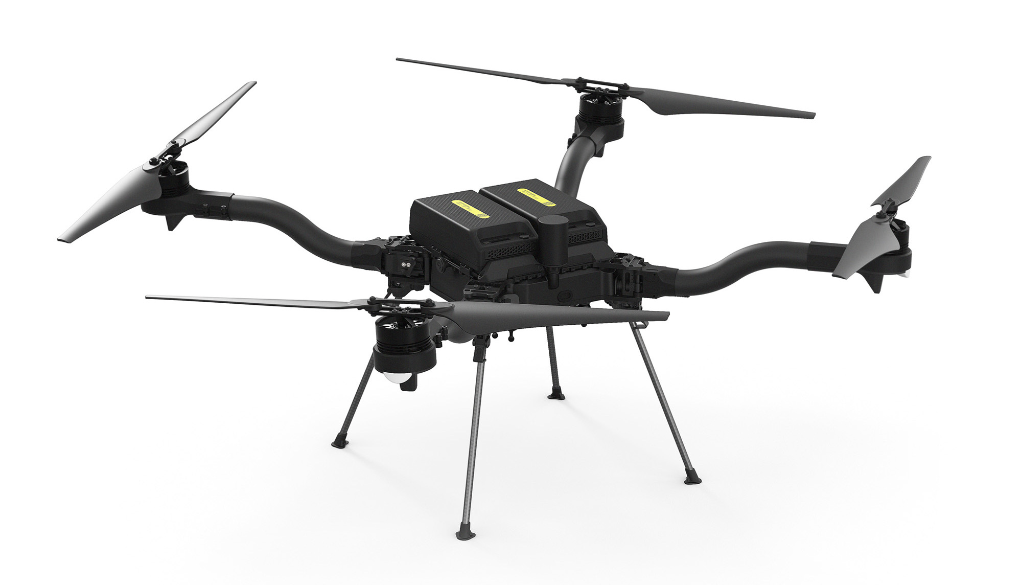
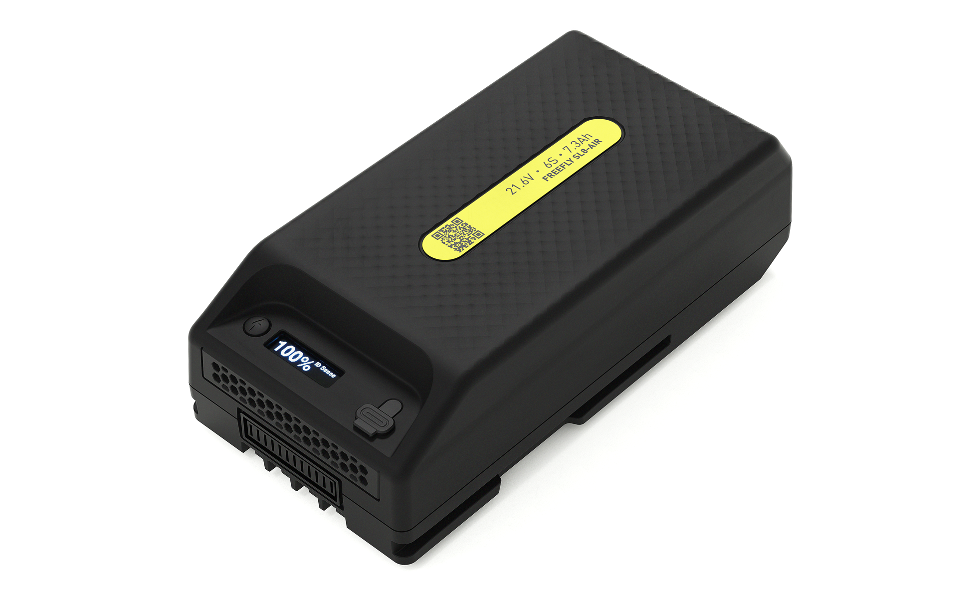
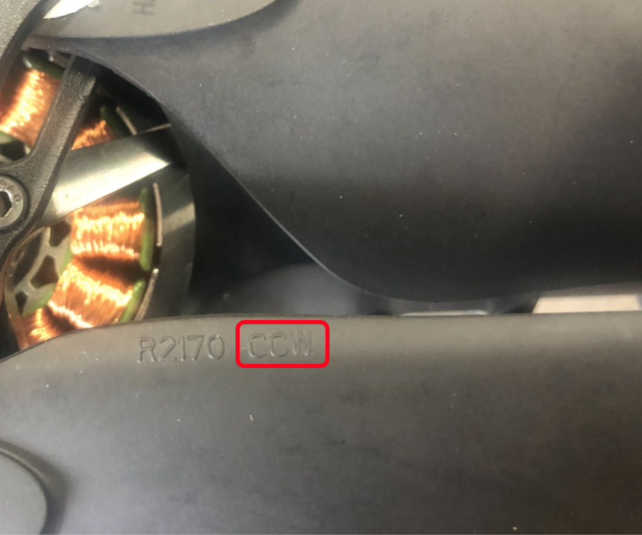
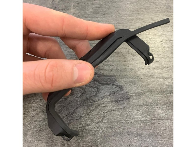
 in the top-left-hand corner of the app.
* Go to Vehicle Setup → Tuning → Hover Throttle
in the top-left-hand corner of the app.
* Go to Vehicle Setup → Tuning → Hover Throttle
